|
WB4HFN Home Page Drake Technical Tips Menu Drake Home Page Collins Home Page Heathkit Home page |
|
Electronic Bias Switching For The Drake Amplifier Written by: Garry Drummond / K4OR E-Mail: g.drummond@verizon.net |
I became interested in bias circuitry for
linear amplifiers in the early 1980's after reading an article
written for QST in 1974 by J.A. Bryant, W4UX. The
article described an electronic bias circuit the author had seen
used in
 the
Alpha 77 amplifier and felt it could be adapted to other amplifiers,
which he proceeded to design and use with success.
Some operators had trouble with the circuit producing distortion on
SSB signals. Marv Gonsior, W6FR (then W6VFR) revised
this circuit in an article that appeared in Ham Radio magazine in
March 1975, to alleviate the distortion problem. I
built several of these electronic bias switches, (EBS) for friends
using SB-220's TL922's and one for myself for a Drake L-7 Amplifier.
Having been off the air from 1990 until 2006, I was curious to see
what the current feeling was on electronic bias switching in today's
environment. I found the trend is toward fixed lower
level idling current rather than a completely cut-off condition the
EBS provided. the
Alpha 77 amplifier and felt it could be adapted to other amplifiers,
which he proceeded to design and use with success.
Some operators had trouble with the circuit producing distortion on
SSB signals. Marv Gonsior, W6FR (then W6VFR) revised
this circuit in an article that appeared in Ham Radio magazine in
March 1975, to alleviate the distortion problem. I
built several of these electronic bias switches, (EBS) for friends
using SB-220's TL922's and one for myself for a Drake L-7 Amplifier.
Having been off the air from 1990 until 2006, I was curious to see
what the current feeling was on electronic bias switching in today's
environment. I found the trend is toward fixed lower
level idling current rather than a completely cut-off condition the
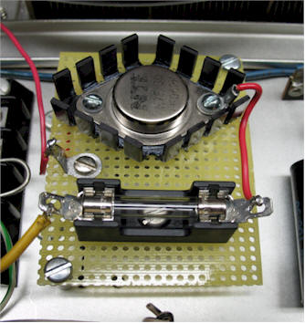
EBS provided.Seeing this, I built a small circuit on a piece of Vectorboard using
just 4 components, a 1-watt 8.2 volt zener diode, a 47 ohm 2-watt
resistor, a 2N3055 pass transistor and a 1 amp fuse. I
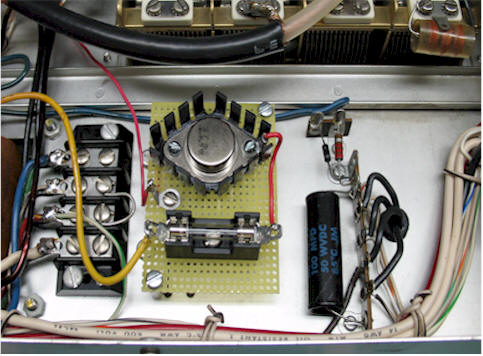
mounted the circuit board in
For reference, if you want more information on the original design or see the circuit diagram. The original circuit is shown in Bill Orr's Radio Handbook 23rd Edition, page 12-27. 73, Garry Drummond - K4OR
|
 the bottom of the RF deck of my Drake
L-4B.
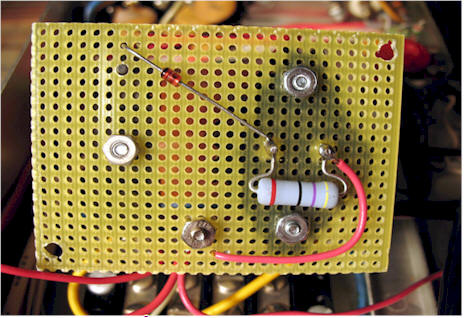
As you can see, I mounted the zener and resistor on the bottom of
the board with the pass transistor and fuse on the top.
This easily fits near the filament transformer and wiring terminal
strip. With this configuration, I have idle current of
40 MA in CW mode and 100 MA on SSB. I also placed
a switch in the circuit to bypass it if I need to. This
may not make any earth shattering difference but I felt if I could
gain even a small amount of efficiency, it was worth the effort.
the bottom of the RF deck of my Drake
L-4B.
As you can see, I mounted the zener and resistor on the bottom of
the board with the pass transistor and fuse on the top.
This easily fits near the filament transformer and wiring terminal
strip. With this configuration, I have idle current of
40 MA in CW mode and 100 MA on SSB. I also placed
a switch in the circuit to bypass it if I need to. This
may not make any earth shattering difference but I felt if I could
gain even a small amount of efficiency, it was worth the effort.