|
The Drake TR-7 Front Panel Transmit Power Control in All Modes By: Jeff Covelli WA8SAJ wa8saj@ncweb.com |
|
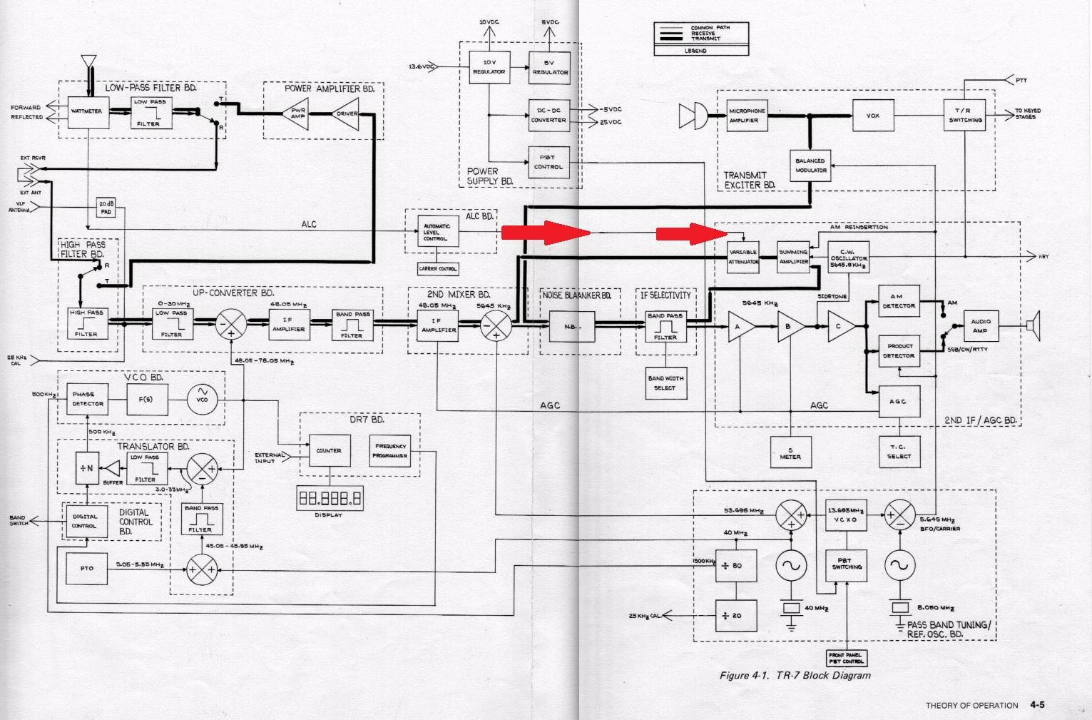
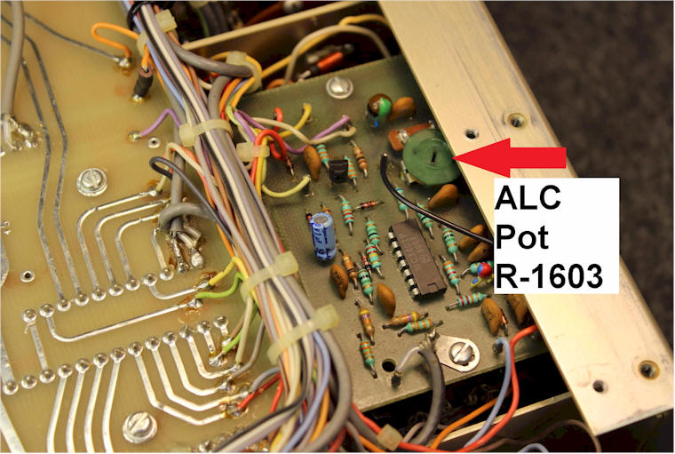
When Drake designed the TR-7 with all new solid-state finals back in the late 70's, there was a little "black magic" involved. Most R.F. Engineers were walking on egg shells trying to get 100 watts out of two transistors. In Drake's case the very informative book "A Family Affair" written by John Loughmiller (KB9AT) states Drake R.F. Engineers struggled for months in getting the final PA amplifier in the TR-7 under control. The book states the PA final can develop about 200 + watts output, yes output. The "ALC" (Automatic Level Control) is the only thing that keeps it all in line at 120 watts output set on 14 MHZ band (later Drake alignment update). This power output is the full "peak" power for CW and SSB, make a note of this for the rest of this article. The "ALC" is on all the time, but on AM/CW mode there is another control on the front panel that actually can force the power lower once the "ALC" control (R-1603) mounted under the chassis is set. What is actually happening, the total control of transmit power is sending a voltage to the 2nd I.F. / Audio Board. The ALC output is actually applying voltage to reduce the drive on the I.F. board (5645 kHz) before it gets to the 2nd transmit mixer and "up converted" to 48.05 MHz. Controlling the drive at this point makes it easy to have better control of the power output evenly. The "ALC"
control mounted under the chassis is used to set the overall total power
output along with the front panel "carrier control" used only for AM/CW
to reduce power after the pre-set of the "ALC" control. Now here
comes the
Before attempting this project, I was going to try and just remove the "ALC" control and use it externally, but this would be catastrophic, since you would have no pre-set level setting safely under the chassis and you could mistakenly develop the 200+ watts out and this would not be a good move! Another thing I found out about the "ALC" board, there are wires from the "ALC" board going to the band switch with resistors mounted on a wafer on the band switch that reduces output on 10 and 15-meters. This was a common practice on many early manufactured solid-state radios such as, Swan, Atlas, Yaesu and Kenwood in the 70's and early 80's to keep the transistors from running away on the higher bands. I have used the front panel carrier control with my Drake L-4B, Hammond HL-1000A and the new Elecraft KPA-500 solid-state amplifier and it works great. It certainly is nice to be able to control the transmit drive on all bands from the front panel now with no problems with distortion with any of the amplifiers. I also use a scope to monitor my transmit signal and keep the pattern looking like a side ways Christmas Tree, no flat topping. I don't use ALC from the amplifiers and I don't recommend it, since it can actually cause IMD distortion. In the Elecraft KPA-500 manual it states "don't use "ALC" to control power output from the amplifier which can cause IMD levels to rise including unwanted transmit dynamics. Procedure For Adding The ALC Jumper 1) Remove top and bottom covers. 2) NOTE: before removing the DR-7 display board, please have the TR-7 grounded and a "static wrist" strap on to keep the display board from having failure due to static! 3) Remove both plastic side panels. 4) Remove the band-switch knob. 5) Remove the 2 screws in the back that hold the band-switch and DON'T twist the band-switch, just slide the whole shaft out towards the back enough to clear the front panel.
6)
Remove the 2 top and middle flat head
screws on the front side of the front panel both sides. Just loosen
the bottom flat head screws and now the front panel will drop
down to access the mode switch.
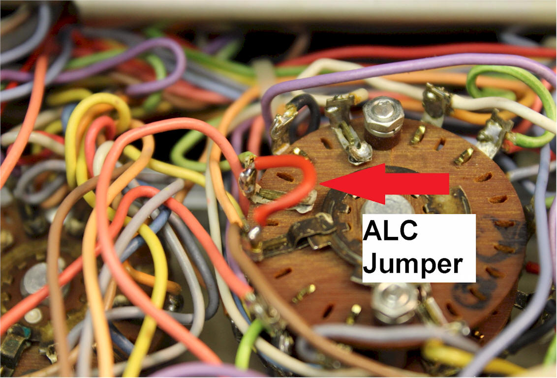
7) Solder a short jumper wire as seen in the picture. 8) Reverse the procedure to put back together. If you ever want to go back to "stock", then just cut the jumper and leave inside for future power control from the front panel for AM/CW only. This was the simplest way to try and control the power in all modes. I've done a few of these for the new low drive solid-state amplifiers and folks say they like ability to control power on SSB and are happy with the change. The procedure for alignment of power output is exactly the same as before the change with the jumper installed. Have fun with keeping the TR-7's going for a long time. 73, Jeff Covelli / WA8SAJ wa8saj@ncweb.com
|
 problem.
Many folks want to drive an amplifier that may only require 20 to 50
watts of drive in SSB mode and this system will not work very well with
the actual "peak" power of 120 watts. In SSB mode just turning the
microphone gain down still develops peaks that the wattmeter does not
see very well, but on a scope is still there. The front panel carrier
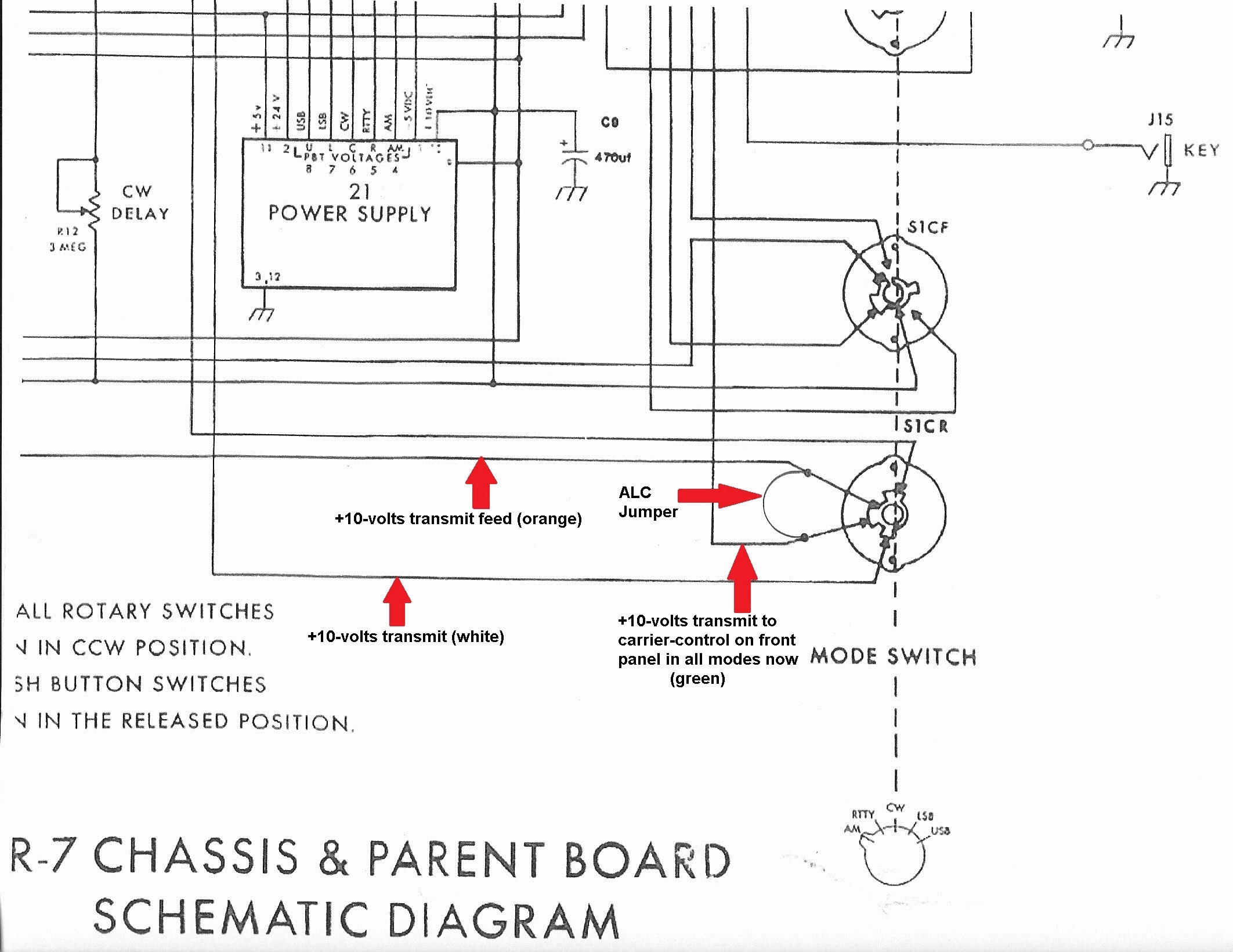
control gets +10-volts in transmit through the mode switch on AM/CW
only. On SSB the +10-volts transmit does not go to the front panel
carrier control. I decided to try and jump out the mode switch allowing
the front panel carrier control to reduce the same drive as the "ALC"
control alone. Most would say not a good move, but really all you're
doing is sending ALC control voltage to the 2nd I.F. / Audio Board
sooner than later compared to the "ALC" pot which still
stays active as before. The only noticeable change in operation is
the "ALC" green lamp will not show up very much in the reduced
power mode, since the front panel control is now doing the work with the
ALC level still being there, but now the green lamp gets a lower voltage
from the "ALC" control, not letting it get lit sooner. The microphone
gain stays the same since this power reduction is done after the
microphone amplifier and balanced modulator stages. The actual ALC
control voltage sent out to the I.F. board is about 1 to 6 volts with a
similar action as before even in the lower power setting, but now you're
in full control of it all in SSB now.
problem.
Many folks want to drive an amplifier that may only require 20 to 50
watts of drive in SSB mode and this system will not work very well with
the actual "peak" power of 120 watts. In SSB mode just turning the
microphone gain down still develops peaks that the wattmeter does not
see very well, but on a scope is still there. The front panel carrier
control gets +10-volts in transmit through the mode switch on AM/CW
only. On SSB the +10-volts transmit does not go to the front panel
carrier control. I decided to try and jump out the mode switch allowing
the front panel carrier control to reduce the same drive as the "ALC"
control alone. Most would say not a good move, but really all you're
doing is sending ALC control voltage to the 2nd I.F. / Audio Board
sooner than later compared to the "ALC" pot which still
stays active as before. The only noticeable change in operation is
the "ALC" green lamp will not show up very much in the reduced
power mode, since the front panel control is now doing the work with the
ALC level still being there, but now the green lamp gets a lower voltage
from the "ALC" control, not letting it get lit sooner. The microphone
gain stays the same since this power reduction is done after the
microphone amplifier and balanced modulator stages. The actual ALC
control voltage sent out to the I.F. board is about 1 to 6 volts with a
similar action as before even in the lower power setting, but now you're
in full control of it all in SSB now.