| Did you ever wonder why Drake designers didn't put a
transmitter key function on the front panel of the TR-7(A) Transceiver
like they did on the Drake TR-5 transceiver. On the TR-5
the far right position on the function switch is "Lock Key".
In this position the transmitter is keyed, a useful function when tuning
up the amplifier or adjusting the antenna tuner. So, Why doesn't the TR-7(A) have a similar
function? I haven't got the answer but I did start
thinking about adding this function to the front panel. The TR-7(A) has no front panel transmitter tuning controls because of it broadband design. That's cool, but how do you key the transmitter without external devices or rear panel switch. Now if your a CW operator, no problem because you probably have some sort of keyer which serves that function. What about the rest of the world that does SSB? There are of course several options but none of which are very convenient. I searched hard and long over the front panel trying to devise a way to add a transmitter key function without adding new holes or switches, and absolutely keeping everything original. I quickly came to the conclusion there wasn't much opportunity unless I wanted to rewire an existing switch. Some time later "light dawned on marble head", as we say here in New England, what about the "Store" switch. What useful function does the switch serve anyway? After reading about the switch in the manual and playing around with it for a while I determined to was fairly useless. So the question came to mind, could I keep the same switch functionally and key the transmitter with the same switch. After some research over the diagram I discovered it was possible. Owning a TR-7 since they were sold new I never used or found a good use for the "Store" switch, but I didn't want to eliminate that function either. Looking at the "Store" switch from the inside, when enabled, it shorts a single wire to ground. The switch is a double pole switch with jumpers across the contacts of both poles creating a single pole action. Since only one side of the switch is needed to turn on the function, by separating the switch poles I now have another set of contacts available. The center contact of the switch is already grounded so its now a simple matter of running a wire from the CW Key Jack on the rear panel of the transceiver to the front of the radio and hook it to the free side of the "Store" switch. Once this modification is done, the "Store" switch still performs its function and remains unchanged. But now when the transceiver "Function" Switch is put into the "CW" position, pressing the "Store" button now keys the transmitter. The switch has a dual function, pressing it in half way for momentary key, push in all the way to latch in place, press again to release. Remember, never key the transmitter for long periods of time. Listed below is the step by step procedure for the modification.
|
|
Shown in the picture below, route the wire under the brown connector plugged into the circuit board. After the connector bend the wire 90 degree and follow the edge of the circuit board towards the rubber grommet. |
|
|
Next shape the wire as shown in the picture, cut wire to the right length and strip back 1/4" of insulation and solder this end of the wire to the high side of the CW Key jack. Refer to the enlarged picture of the CW Key Jack showing this connection. The High side will have a single wire attached. The other side of the CW Key Jack is ground potential and has a large coil and spark suppressor soldered to it. Next reinstall the Receiver IF/Audio board. This now completed the modification installation. |
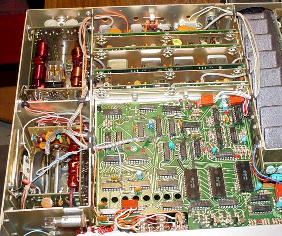
Next you will test to make sure everything is working. Attach the transmitter to a 50 ohm dummy load, set the front panel function switch to the "CW" position and push in the "Store" switch. The transmitter should key and output power according to the set position of the "Carrier Level" control. When using this to tune up your amplifier or adjust the antenna tuner use only the minimum amount of power needed to make your adjustment and never key the transmitter for long periods of time. This now completes the circuit test, reinstall the case and your done. When keying the transmitter current draw is the same whether power is at minimum or at full output, so ther is no concern of damaging the switch or radio. The picture below shows the entire route of the wiring, see the orange wire as it route its way from the front panel switch to the rear panel area. If at any point you want to put the radio back to its original condition simply reverse this process and it less than 5 minutes its removed and back to its original condition.
|
 First remove the case and locate the
"Store" switch contacts just behind the front panel. You will
notice a white wire going to one side of the switch contact near the rear
of the switch. Also notice both sides of the dual section switch are shorted
together. Current flow through this switch is small so using only
one side of the switch will work just fine.
First remove the case and locate the
"Store" switch contacts just behind the front panel. You will
notice a white wire going to one side of the switch contact near the rear
of the switch. Also notice both sides of the dual section switch are shorted
together. Current flow through this switch is small so using only
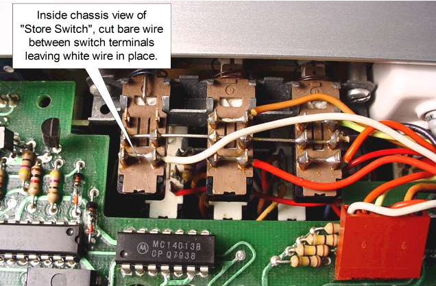
one side of the switch will work just fine.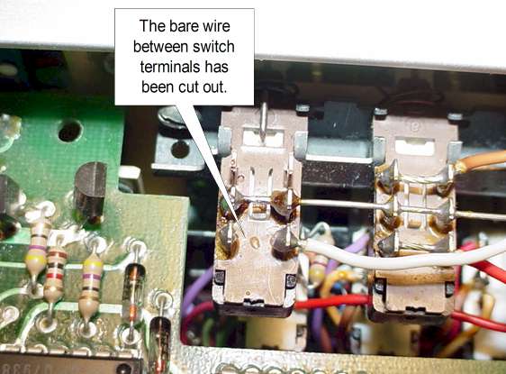 Once you locate the switch and contacts you need to cut the
small jumper wire between the rear most set of contacts as shown in the
picture. Cut the jumper between the contacts, do not cut the white
wire. That wire will remain in place.
Once you locate the switch and contacts you need to cut the
small jumper wire between the rear most set of contacts as shown in the
picture. Cut the jumper between the contacts, do not cut the white
wire. That wire will remain in place.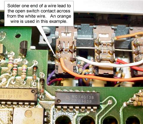 In the next step you will need an 18" piece of wire.
Strip bare one end of the wire about 1/4" and solder that end to the open
switch contact as shown here in the picture. After
the wire is soldered in place route the wire around the radio
through rubber grommets to the rear panel of the radio.
As shown here shape the wire so it curves and follows the edge of the
adjacent circuit board.
In the next step you will need an 18" piece of wire.
Strip bare one end of the wire about 1/4" and solder that end to the open
switch contact as shown here in the picture. After
the wire is soldered in place route the wire around the radio
through rubber grommets to the rear panel of the radio.
As shown here shape the wire so it curves and follows the edge of the
adjacent circuit board.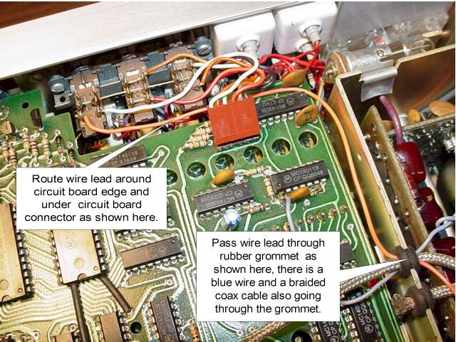 Going through the rubber grommet you will see a blue or purple wire and a
braided coax, feed the free end of the wire
through this same grommet as shown here in the picture. Once
the wire is through this grommet route the wire straight back through this
section to the next grommet in line.
Going through the rubber grommet you will see a blue or purple wire and a
braided coax, feed the free end of the wire
through this same grommet as shown here in the picture. Once
the wire is through this grommet route the wire straight back through this
section to the next grommet in line.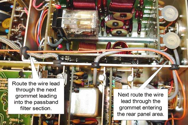 Route the wire through the second grommet as shown here.
Shape the wire so it travels as shown in the picture to the rear panel.
Next route the wire through the rear grommet which enters the rear panel
area. Again shape the wire to travel as shown here in the picture.
Route the wire through the second grommet as shown here.
Shape the wire so it travels as shown in the picture to the rear panel.
Next route the wire through the rear grommet which enters the rear panel
area. Again shape the wire to travel as shown here in the picture.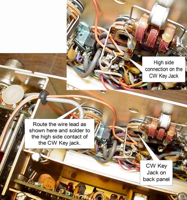 Once the wire is in the rear panel area you should remove the
Receiver IF/Audio board to gain better access to the work area.
Once the wire is in the rear panel area you should remove the
Receiver IF/Audio board to gain better access to the work area.