|
This write up will
cover the basics of how the PTT circuit in the TR-3 through TR-4CW and T4X
series transmitters works. Non specific trouble shooting aids are supplied
that pertain to any of these models. The PTT circuits in the different
models are slightly different, but are functionally alike. This article
teaches the basics and is not meant as a guide on specific fixes.
The
Basics: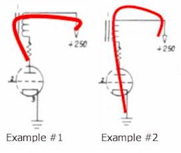
Before you can get
any relay energized,
you need a path for the
current to flow through the relay coil. In this case it’s designated as
K1. In this first example, you have the correct voltage, +250VDC from the
supply all the way to the plate of the tube. If the tube is cut off, there
will be no current path to ground. There is usually a small negative
voltage (-10 VDC) on the grid of the tube when in the receive mode. In
this example it’s pin #2. This cuts the tube off in the receive mode. If
you ground pin#2, the tube will turn on and current now can flow. Once you
have current flow, the relay will pull in. If you check the plate
voltage, Pin #1 in this example, it will drop from it’s normal
+240 - 250 VDC to anywhere from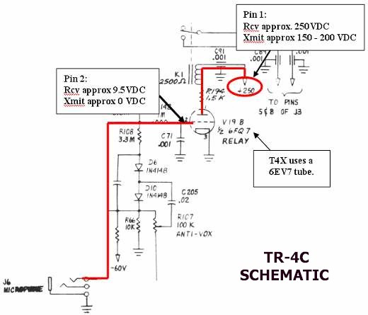 150
– 220 VDC, model dependant, when pin #2 is grounded. If you follow the
circuit through to the mic
connector, the grid will
connect to the tip of the mic plug. When the PTT button is pressed, the
tip is grounded and pin #2’s
negative voltage now will go to zero, which now lets the tube
conduct and pull in the K1 relay.
The function switch will also ground this connection when it’s moved to
the X-CW position on the TR-3 through TR-4C, or the Tune position on the
T4X series of transmitters. 150
– 220 VDC, model dependant, when pin #2 is grounded. If you follow the
circuit through to the mic
connector, the grid will
connect to the tip of the mic plug. When the PTT button is pressed, the
tip is grounded and pin #2’s
negative voltage now will go to zero, which now lets the tube
conduct and pull in the K1 relay.
The function switch will also ground this connection when it’s moved to
the X-CW position on the TR-3 through TR-4C, or the Tune position on the
T4X series of transmitters.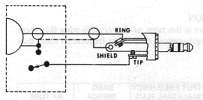
Typical
Problems:
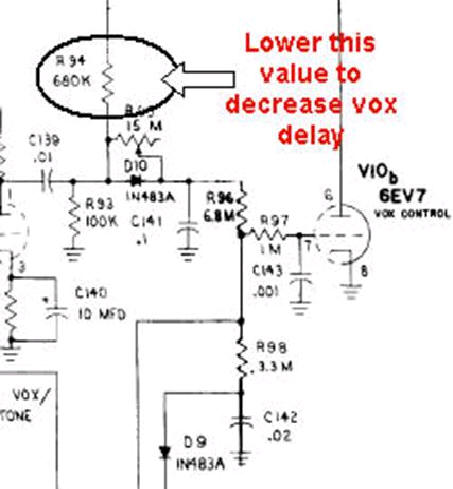
- The most likely
problem is the Vox control tube (V19b in TR-3 to TR-4C models and V10b
in the T4X to T4XC models). The tube (6EV7 or 6FQ7) gets gassy or weak
and either the relay will not energize, or its operation becomes very
erratic. Replace the tube with a new one. Do not trust a tube tester to
tell you if it’s good or bad. The best method is utilizing a NOS (New
Old Stock) tube from a reliable source.
- The AC3 - AC4
power supply +250 volts supply could be bad. Make sure you have 240 –
260 VDC at the plate of the Vox tube. If no voltage is present, the
diodes have probably gone out and will need replaced. Also check the AC
ripple. If excessive, the filter capacitors in the AC3 – AC4 need
replaced.
- The AC3 – AC4
bias supply could be bad. The voltage should be around -40 to –60 VDC.
If it’s not, make adjustment to the bias adjustment control located on
the supply per the instructions in the manual. If no voltage is present,
the diodes have probably gone out and will need replaced. Also check
the AC ripple. If excessive, the filter capacitors in the AC3 – AC4 need
replaced.
- The Anti Vox
potentiometer is not adjusted correctly. If the Anti Vox is adjusted to
sensitive, it will not let the transmitter relay to turn on. The Anti
Vox pot needs to be adjusted so that when receiving a station, at
comfortable listing levels, you can activate the relay. In the above
circuit, you can see where the Anti Vox signal ties into the same point
as the PTT from the voltage generated in the audio amplifier. If it’s
adjusted to sensitive, you will notice when you turn the volume all the
way down, the relay works.
- The circuit path
between the mic plug tip and the grid of the Vox tube is not good. You
can take an ohm meter and verify there is very low resistance ( <1 ohm)
between the mic plug and the grid input resistor, R142 in the TR4C. Your
resistance should change as press the PTT button.
- You can take a
jumper wire and with one end grounded put the other end on the grid
input resistor, R142 in the TR4C. With a good 250 VDC on the plate, the
relay should pull in. If the relay does pull in, but does not when using
the Mic, the problem is in the PTT line of the microphone.
- If the relay
seems to be activating ok, but intermittent results are obtained,
cleaning could be in order. See the separate write up on “Relay Care”
which covers cleaning on the relay contacts.
- If the relay
hangs up, even after the tube has been removed for trouble shooting, the
following possible fixes were suggested have been made others.
|