Adapting the IQPro VFO to the Drake TR7
Written By: Floyd Sense - K8AC
Angier, North Carolina
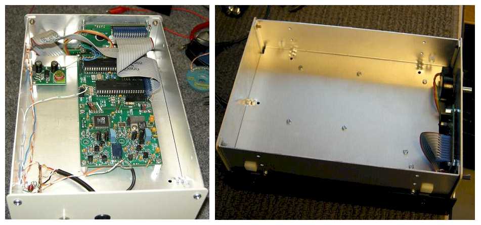
The VFO is housed in a TenTec cabinet with a front panel measuring 4x6". The length of the cabinet is 9" and as you'll see I could have used a cabinet of about 6" depth with no problem.
|
|
Lots of room inside with the IQPro boards still joined together. They could be split and stacked in a shorter cabinet if desired.
|
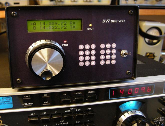
Here you can see my modified LCD display which shows both VFOs on the LCD at the same time. In SPIT mode, the RX - TX tags show which VFO will be used for receive and transmit. To the left of the VFO designator (A or B) is a right arrow that points to the active VFO. If the PTT line were grounded at this point, the arrow to the left of the A would move down to the left of the B indicating that VFO is now controlling the frequency of the TR7. When the VFO is not is split mode, the active VFO is identified with an R/T tag to the right of the frequency.
|
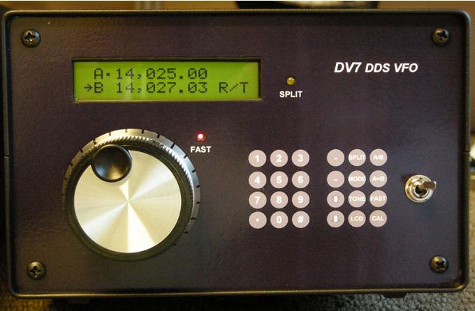
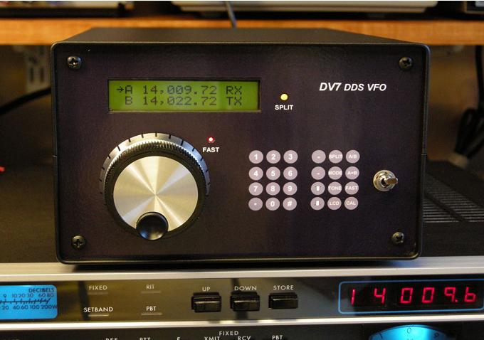
When not in split mode, the R/T tag identifies the VFO being used for both receive and transmit. Note the small square to the right of the A - that indicates we're in CW or CW-R mode. In this application, it's necessary to know only if we're in CW mode because of the offset applied to receive in CW mode and the fact that the TONE function operates only in CW mode.
|
|
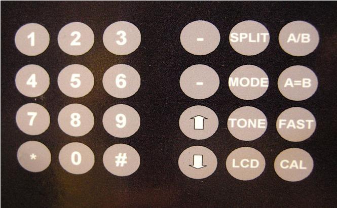
Here's a close-up of the keypad buttons, printed on the front panel sheet. The buttons extend just slightly beyond the front of the panel and the sheet is flexible enough to allow the individual buttons to easily be pressed. This idea came from VU3WIJ. |
| Floyd Sense - K8AC
Link To VFO Article |