|
Adapting the IQPro VFO to the Drake TR7 Written By: Floyd Sense - K8AC
|
|
| The following
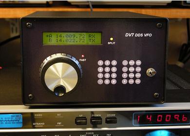
documents what I've learned in adapting the IQPro DDS VFO for use as an external VFO for the Drake TR7 transceiver. The ultimate goal is to replace the TR7 internal PTO with the IQPro, but using the TR7's existing RV7 interface was an attractive first step since it required no modifications to the TR7 at all. When using an external VFO with the TR7, the TR7's digital readout will always read the correct frequency. As of December 30, 2007, I have the prototype of the VFO running successfully with my TR7. Extensive changes were made to the IQPro PIC code to adapt the VFO operation to my desires. Differences between the IQPro and RV7 The Drake RV7 remote VFO is of course a single PTO, basically the same PTO that is used in the TR7. If turned off, it has no effect on TR7 operation at all. When turned on, the function switch selects whether the RV7 will be used only on Receive, for Receive and Transmit, or only for Transmit. The IQPro features two separate VFOs (A&B) and I elected to have the IQPro control the Receive and Transmit frequencies completely when it's turned on. I saw no need to duplicate the RV7 ability to have the TR7 PTO control transmit or receive while the IQPro controlled the other. The two VFOs in the IQPro made that function superfluous. Aside from the increased temperature stability of the IQPro, my main reasons for using it was to achieve a lower tuning rate (fewer Khz per knob revolution) commensurate with more modern gear, and a simpler split frequency capability. The TR7 - RV7 Interface The RV7 connector on the rear panel requires an 8 pin Jones plug, no longer available. However, Molex makes a replacement for the Cinch Jones part (details on source go here). The TR7 and RV7 diagrams go out of their way to confuse the reader (which side of the connector am I looking at?) and for some reason they don't show the horizontal and vertical orientation of the connector pins. So, here's the pin-out information and you can look at the connector to see where pin 1 is. Pin 1 - Ground 2 - VFO RF Out (This one is interesting, since the RV7 also applies a 13.6VDC to the RF line in order to operate the PIN diode that must conduct to switch the RV7 RF into the TR7 translator input.) 3 - 13.6 VDC (This is used to power the IQPro) 4 - Transmit disable (In the RV7, this line is grounded by the spot switch to disable the TR7 transmitter when adjusting the TR7 and RV7 VFOs to the same frequency using the Spot switch. The function is not necessary and not used with the IQPro. 5 - RV7 Enable (When the RV7 function switch is not OFF, the TR7 applies a +DC voltage to this line. The circuitry that does that is driven by pins 7 and 8 of the connector, indicating to the TR7 which VFO to use for Receive and which for Transmit. This same voltage is applied to Pin 2 by the RV7 as described above. So, if the RV7 is NOT to control the receive or transmit frequency, there will be no voltage on this pin in that mode and therefore no RF output from the RV7). 6 - RIT line (This line has a low voltage on it, controlled by the RIT pot on the TR7 front panel. It is used to change the capacitance of a varicap in the RV7 oscillator circuit, but has no function for the IQPro at this time.) 7 - "A" in diagrams, the RV7 applies 13.6VDC here to indicate that the RV7 will control the TR7 frequency in Receive mode. 8 - "B" in diagrams, the RV7 applies 13.6VDC here to indicate that the RV7 will control the TR7 frequency in Transmit mode. If the RV7 will control the frequency in both Receive and Transmit, both pins 7 and 8 will have 13.6VDC applied. Additional IQPro Interface Requirements In the IQPro, if you're operating in split mode using VFO A for receive and VFO B for transmit, you need a way to tell the IQPro when you're in transmit mode. The way you do that is to short the two pins of Header 6 on the Interface board. If you're not using an amplifier, the easiest way to do that is to use the VOX Relay jack on the PS-7, which grounds the center pin when the TR7 goes to transmit mode. A second approach, and one that I now use, is to pick up the 10V transmit line on pin one of the Accessory connector and use that signal to switch a 2N3904 transistor connected across Header 6. That requires a 12 pin Jones connector, but those are still available from Jameco and other sources. I wanted to avoid using a function switch in the IQPro VFO so it was necessary to hardwire some of the RV7 interface function normally provided by the RV7. Turning on the IQPro will tie RV7 connector pins 7 and 8 to the 13.6VDC line (pin 3), indicating to the TR7 that the IQPro will be used for both receiving and transmitting. In order to use any remote VFO with the TR7, a positive DC voltage must be applied on the VFO's RF output. That switches a PIN diode in the TR7 gating the remote VFO signal to the translator board. I supplied 13.6VDC from the IQPro power switch to the RF output terminal via a small RF choke. The TONE frequency for the IQPro should be set to 0 Hz. The TR7 accomplishes the CW offset elsewhere and using an offset on the VFO frequency will assure that your CW transmit frequency will be different from your receive frequency - not a good thing. IQPro Output Level On my IQPro RF board, I use the "I" output with the transistor amplifier enabled, but no toroid installed. In setting the output level of the IQPro, I measured (using a scope) the PTO signal voltage on the pin labeled "PTO" on the bottom of the TR7 parent board. Using the internal PTO, the signal there was .6V peak-to-peak. I then connected the IQPro and adjusted R43 for .6V p-p at the same point. The output level at the "I" terminal of the RF board measured 1.5V p-p. IQPro Hardware Changes I wanted to keep the VFO front panel as simple as possible so decided to limit my use of the LEDs to just two: One next to the LCD display to indicate SPLIT mode, and another near the tuning knob to indicate FAST-TUNING mode. If necessary, you can always plug the full LED strip into the header to see the status of the other LEDs. IQPro PIC Code Modifications Required First, I want to make it clear that you won't need any changes to the PIC code to get the VFO working with the TR7. The TR7 readout will continue to work properly and the only catch is that the IQPro LCD will not show the operating frequency, but rather the VFO output frequency. To use the VFO in this way, you just power it up, enter the operating frequency of 5.050 MHz via the keypad, and you're ready to go on all bands. You never need to use the band up/down buttons. The second possibility is to use the IQPro with the existing LCD formats (nothing at all wrong with that), in which case you'll just need to modify the band table to include the offsets for each band. That will get you all bands, but only the first 500 KHz of 10 meters. A deficiency in the code prevents you from adding segments to the band table for the rest of 10 meters at this time. If you really want to add those segments, my TR7 version of the code includes them, and has fixes the problem of not being able to expand the band table. The only other reason for using my version of the code is if you prefer my LCD layout to the original. The principal difference is I show both VFOs on the LCD all the time, while the original code shows one VFO at a time. The ability to specify an IF offset is already in the IQPro code, and only minor modifications are required to use the TR7. The problem is that the TR7 VFO operates over the range of 5.05 to 5.50 Mhz regardless of the band you're operating on. Using the IF offset table in the code enables the LCD to read out the correct band and operating frequency, while telling the DDS to generate the appropriate frequency in the 5.05 to 5.50 Mhz range. Since that offset is different for each band (and 10 meter band segment), the offset had to be calculated for each segment and those values put into the offset table. The must be expanded by three rows to cover the complete 10 meter band. My code covers only up to 29.5 MHz with two additional rows since the TR7 doesn't have an FM capability anyway. |
|
| Additional Changes to the PIC Code |
|