|
Installation
The Digital-Dial and the Buffer/Clipper, come
with all the connectors for power and a couple of RCA phono plugs, for the
R.F. I started installing the Buffer/Clipper first by trying to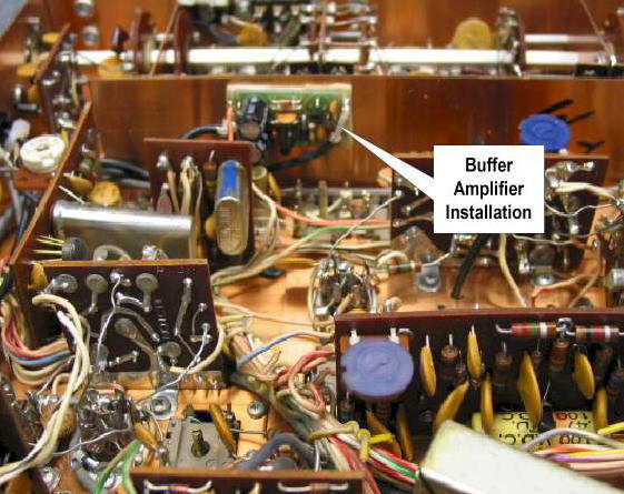 locate a
spot on the bottom side of the chassis in the R-4B that would not impede
any future work like alignments, etc. There was a spot
near V-3 12BE6 in between the I.F. cans and on the side-panel not far from
the injection point, where the frequency input has to go. I used good old
“double-sticky” tape, which works great for mounting. I picked off the
6.3-volt filament for the Buffer/Clipper from V-2 6HS6 not far away. The
Buffer/Clipper has a rectifier and filter installed already, so there is
no need to supply D.C. to it. I used RG-174 (50-ohm) coax cable to tap off
the “frequency-injection” jack, this is the pre-mixer output for the R-4B,
more on this later. The Buffer/Clipper now has a high locate a
spot on the bottom side of the chassis in the R-4B that would not impede
any future work like alignments, etc. There was a spot
near V-3 12BE6 in between the I.F. cans and on the side-panel not far from
the injection point, where the frequency input has to go. I used good old
“double-sticky” tape, which works great for mounting. I picked off the
6.3-volt filament for the Buffer/Clipper from V-2 6HS6 not far away. The
Buffer/Clipper has a rectifier and filter installed already, so there is
no need to supply D.C. to it. I used RG-174 (50-ohm) coax cable to tap off
the “frequency-injection” jack, this is the pre-mixer output for the R-4B,
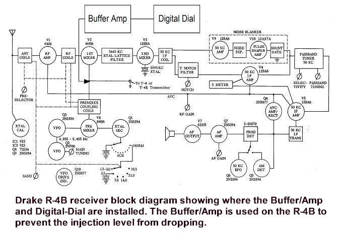
more on this later. The Buffer/Clipper now has a high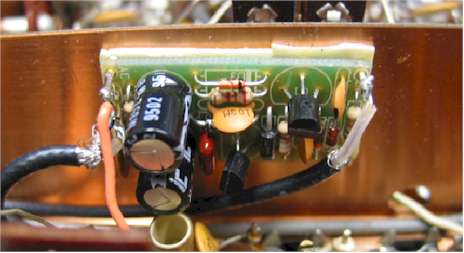 impedance input,
so it will not pull the injection level down and passes along the
frequency to the Digital-Dial. It also maintains a constant level
for the output, as the input varies. The output cable is also RG-174
(50-ohm) coax and I run it and the 12-volt dc out an open hole on the rear
of the R-4B. The cables are then put together with tie wraps for about 3
feet, just the right length to feed the Digital-Dial. impedance input,
so it will not pull the injection level down and passes along the
frequency to the Digital-Dial. It also maintains a constant level
for the output, as the input varies. The output cable is also RG-174
(50-ohm) coax and I run it and the 12-volt dc out an open hole on the rear
of the R-4B. The cables are then put together with tie wraps for about 3
feet, just the right length to feed the Digital-Dial.
|