|
High Voltage
Transformer Installation
The first challenge when
looking for replacement parts was finding the right high voltage
transformer that not only is the right size to fit the chassis, but having the right voltage and
current capabilities.
I searched several sources for a compatible high voltage
transformer and settled on the transformer from a Heathkit
SB-220 Amplifier. The transformer seemed to be a
good fit, it does produce a little more
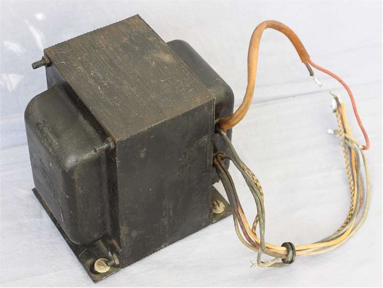 high voltage, and it is
a bit smaller than the transformer in the original L4PS power
supply. It has the
dual 110VAC primary windings to operate at 110 or 220VAC and has
tapped secondary high voltage windings for the "Tune" and "Operate"
Modes. high voltage, and it is
a bit smaller than the transformer in the original L4PS power
supply. It has the
dual 110VAC primary windings to operate at 110 or 220VAC and has
tapped secondary high voltage windings for the "Tune" and "Operate"
Modes.
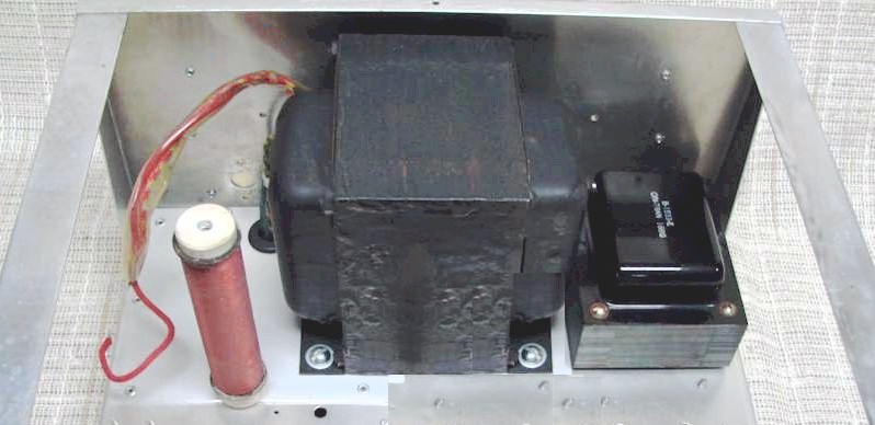
As shown
in the picture below I mounted the transformer along the back of
the chassis as close to the filament transformer as practical.
I did this so I had maximum space to mount the power supply
board on the opposite side and to allow for good air flow for
cooling. The aluminum plate I installed earlier
provided a solid mounting surface for the transformer.
I ran the primary winding under the chassis in the back corner
and the high voltage secondary winding were left above the
chassis to connect with the power supply circuit board.
I also mounted the plate choke to the left of the transformer to
give me the proper distance to reach the tube and prevent arcing
to the transformer.
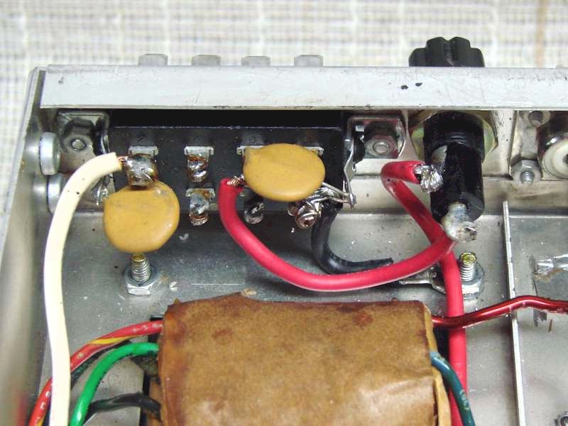
Under the
chassis, shown below, I brought the both primary windings to a terminal strip
so it could easily be wired to operate at 110 or 220 volts.
Each primary winding is a tapped winding which is used to switch
between the the "Tune" and "Operate" modes.
Since that switching is the same for either the 110 or 220 volt
operating voltage I used a small
relay to do that switching. This way I eliminate the vulnerability of the power switch
contacts from arcing internally and welding together due to the
high current being switched. This is a very common
problem in that power switch which prevents it from switching
between the "Tune" and "Operate" mode.
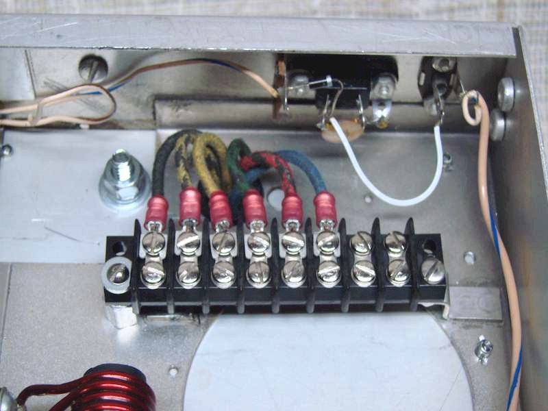 
The photo on the left shows the transformer
primary wiring to the terminal strip. From left to right
the two primary winding are in groups of three wires
In each group the black dual color stripped wire is the
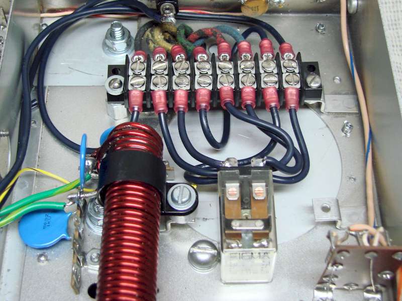
tapped connection to the winding. In the picture on the
right shows the wiring for 220 VAC operation. The relay
switches the winding tap connections for the "Tune" or "Operate"
mode. The difference being lower high voltage
for amplifier tune-up purposes. Power output
between "Tune" to "Operate" is approximately 150 watts of
additional power. The relay now operates from the front
panel "Tune / SSB" switch to the low voltage power supply.
This eliminates the common problem of the front panel power
switch arcing and welding the switch contacts together.
The large 8 pin connector on
back of the L4B chassis, originally connected to the L4PS power
supply is now the primary power connector for the new design.
The connector, depending on how the amplifier is jumpered
internally, will except either a 110VAC / 220VAC input. The circuit
breaker protection for the amplifier was originally in the L4PS
power supply. In my design there is very little rear
chassis space to accommodate circuit breakers so I decided to
use fuse holders. Since there are now two
transformers each receiving primary power, I decided to install
a separate fuse holder for each one. Shown in the picture
to the left next to the 8 pin power connector is the chassis
mounted fuse holder for the filament transformer.
The high voltage transformer fuse holder is the same type fuse
holder but
mounted on the other end of the chassis near the high voltage
transformer. Both fuse holders use a 15 AMP fuse for
110VAC or 10 AMP fuse for 220VAC.
|