WB4HFN Home Page Drake Technical Tips Menu Drake Home Page Collins Home Page Heathkit Home page
![]()
|
HOMEBREWING THE DRAKE 1544 RV75/R7 ADAPTER by: Lee Craner WB6SSW
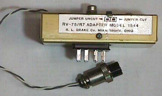
I have enjoyed owning my Drake TR7A since the early 80’s. Over the years, I have also picked up the matching R7A receiver and the RV75 digital VFO. However, try as I might, I never have been able to pick up the Drake 1544 adapter that is necessary to connect the RV75 to the R7A.The Drake 1544 adapter (figure 1) is a small box that plugs into the “Accessory” socket in the back of the R7 or R7A. The RV75 plugs into the adapter box to give the R7 rock solid frequency stability, variable rate tuning and two programmable fixed frequencies. Transceive capability between the TR7 and the R7 is retained by plugging the TR7/R7 transceive cable into the 1544, rather than the accessory socket of the R7. (An original TR7/R7 transceive cable is also tough to find. WB4HFN makes a great clone of the original Drake cable). A short two wire cable running between the 1544 and the R7’s 13.8VDC accessory socket powers the RV75.
|
| The prepared Hammond 1590A box. Note that the 12 pin connector holes are opposite each other. |
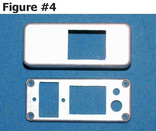
I prepared the utility box by cutting the holes for the three Cinch connectors, the RCA phono jack and the grommet for the power cable. The holes for the Cinch connectors were cut to be just big enough to accommodate the front of the connectors. The hole for the twelve pin plug was cut in the bottom of the utility box and slightly offset from center to clear both the R7’s voltage select slide switch on the left and the speaker jack on the right (see figures 4 and 7). The hole for the twelve-pin socket was cut in the lid exactly opposite the hole in the box’s bottom.
The Cinch sockets and plug are designed for chassis mounting (that is, they have what Cinch calls angle brackets) and may be hard to find. However, the twelve-pin socket and plug do not necessarily need the angle brackets, as I’ll explain later on. The eight-pin socket will need the angle bracket, though.
The angle brackets (mounting tabs) of the Cinch Jones 12 pin plug and socket are too big to allow mounting in the box. Therefore, I had to shorten these brackets at about the middle of the mounting holes, so that they just fit the inside of the box (since the plug and socket would “float” in the box, the bracket mounting holes weren’t needed). Note if you have a plug or socket that doesn’t have the brackets, you can simply epoxy a small piece of scrap metal or plastic to the sides of the plug or socket. The idea is create a plug and socket that won’t fall through either hole you cut in the box.
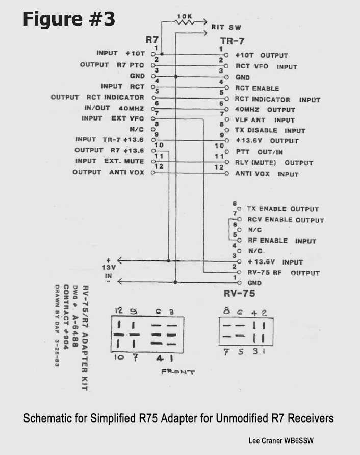
Referring to the schematic in figure 3, you’ll note that nine pins of the Cinch Jones 12 pin plug and socket are wired “straight through,” pins 1-6, 9, 11 and 12. Also, note that pins 7, 8 and 10 of the socket are unused. So, I cut off the solder end of pins 7, 8 and 10 in order to prevent these pins from shorting to the corresponding pins of the plug. I then wired the Cinch Jones 12 pin plug and socket together back to back, by soldering corresponding plug and socket pins 1-6, 9, 11 and 12 together using small pieces of 22 ga single strand hookup wire. As luck would have it, the resulting assembly height was the same depth as the Bud box. This allowed the assembly to “float” in the adapter, held in place by the angle brackets and the cutouts in the box that were just big enough for the front of the connectors.
| The completed 12 pin plug and socket. Note the shortened brackets. |
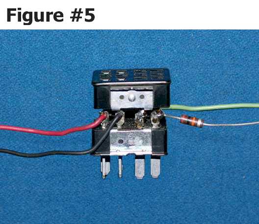
I attached a length of 22 gage multistrand hookup wire to pins 3, 7 and 10 and one leg of the 10K resistor to pin 1 of the Cinch Jones 12 pin plug. The completed assembly is shown in figure 5.
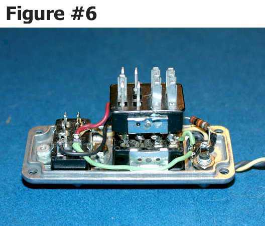
Using the R7 accessory jack to correctly orient the polarized plug, I laid the assembly into the box lid. After jumpering pins 5 and 7 of the Cinch Jones 8 pin socket connector (as shown in figure 3), I mounted the 8 pin socket connector, the RCA phone jack and the chassis grommet to the lid of the box. Using the schematic (figure 3) as a guide, I finished wiring the three loose wires and the other end of the 10K resistor to the Cinch Jones 8 pin socket connector and RCA jack (figure 6).
| The wired adapter. The 12-pin plug and socket simply “float” in the finished box. |
I completed the adapter by fastening the box lid to the box using the supplied machine screws, and then plugged the adapter into the accessory plug of the R7. I found that a more secure fit to the R7 was achieved by removing the interfering screw that helps secure the R7’s input voltage selector plate.
| The installed adapter. |
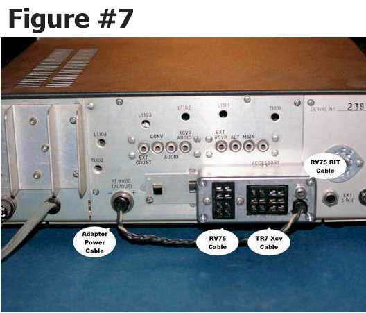
Cabling the new adapter simply meant plugging the RV75’s two cables into the adapter and plugging the adapter’s Amphenol plug into the R7’s Amphenol 13.8V socket (this is the source that powers the RV75). See figure 7.
In order for the RV75 to control the R7’s frequency it is necessary to push in the R7’s “fixed” button. To revert back to the R7’s internal VFO, turn the RV75 to off and leave the “fixed” button in the out (off) position.
If you choose to duplicate my adapter, would you please let me know how it worked out for you by sending an email to me at leecraner@aol.com?
73, Lee Craner WB6SSW