|
This modification allow you
to upgrade the low voltage power supply in the Drake R4C receiver
utilizing the existing circuit board. This eliminates installing
an after-market circuit board and replacing the old audio amplifier
circuit because of its high current requirements. During the
construction you may want to refer the before and after circuit diagram links below to
compare. First you will need to remove
several components, the diodes CR18 and CR19, resistors R115 and R115
these are the two 5
 watt resistors, capacitor C47 and the pass
transistor Q2. Next remove the wire from the +150VDC
supply feeding the PTO circuit, and remove the white wire from
the regulated
low voltage source feeding the audio amplifier, make sure you cut the
right wire since there several wire at this point. Next
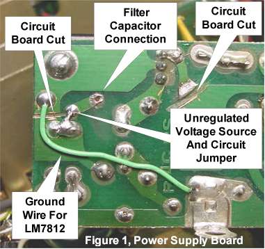
make two circuit board cuts as shown in Figure 1. Next install the
LM7812 IC regulator and heat sink exactly the same way the pass
transistor Q2 was mounted, see Figure 2 for details. Next install
a ground wire jumper as shown in Figure 1 to provide a ground path for
the regulator, and install the circuit pad jumper between the
unregulated voltage supply to the unused circuit trace as shown in
figure 1. The unused trace you jumpered to will be the input
connection to the filter capacitor, that wire in inserted to the board
from the component side of the board.
watt resistors, capacitor C47 and the pass
transistor Q2. Next remove the wire from the +150VDC
supply feeding the PTO circuit, and remove the white wire from
the regulated
low voltage source feeding the audio amplifier, make sure you cut the
right wire since there several wire at this point. Next
make two circuit board cuts as shown in Figure 1. Next install the
LM7812 IC regulator and heat sink exactly the same way the pass
transistor Q2 was mounted, see Figure 2 for details. Next install
a ground wire jumper as shown in Figure 1 to provide a ground path for
the regulator, and install the circuit pad jumper between the
unregulated voltage supply to the unused circuit trace as shown in
figure 1. The unused trace you jumpered to will be the input
connection to the filter capacitor, that wire in inserted to the board
from the component side of the board.
Circuit
Diagram BEFORE Modification Circuit
Diagram AFTER Modification
Next connect the wire you
removed earlier which goes to the PTO circuit, this now attaches to the
+12VDC regulated output from the regulator.
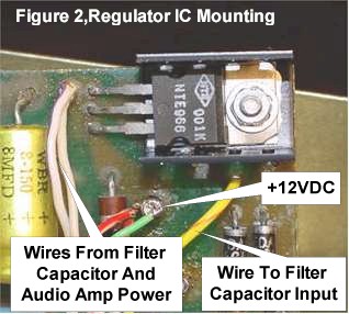 Next attach the
wire providing power to the audio amplifier board and the wire from the
filter capacitor output, to the unregulated
voltage input to regulator as shown in Figure 2. Figure 3
shows the power supply low voltage filter capacitor with the two wires
from the power supply board and the 1 ohm resistor between the two
filter sections. The last step is to install an additional
2700uf/25Vdc axial lead filter capacitor from the output connection of
the LM7812 regulator to ground. This filter capacitor provides
extra filtering in the +12Vdc regulated supply to eliminate hum in the
audio. This
now completes the actual modification, by referring to the pictures and
diagrams someone familiar with
circuit board work and basic troubleshooting skills can easily figure
out this Next attach the
wire providing power to the audio amplifier board and the wire from the
filter capacitor output, to the unregulated
voltage input to regulator as shown in Figure 2. Figure 3
shows the power supply low voltage filter capacitor with the two wires
from the power supply board and the 1 ohm resistor between the two
filter sections. The last step is to install an additional
2700uf/25Vdc axial lead filter capacitor from the output connection of
the LM7812 regulator to ground. This filter capacitor provides
extra filtering in the +12Vdc regulated supply to eliminate hum in the
audio. This
now completes the actual modification, by referring to the pictures and
diagrams someone familiar with
circuit board work and basic troubleshooting skills can easily figure
out this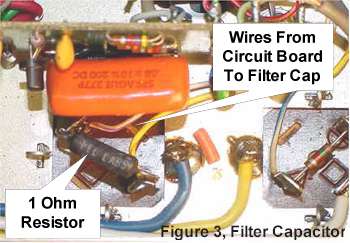 modification.
The
LM7812 IC regulator and small heat sink are both available from Radio
Shack for under $10.00. Since the audio amplifier is no longer
connected to the regulated side of the circuit the remaining current
draw is small requiring a minimum amount of heat sink. Even though
the audio circuit is now unregulated I've detected no difference in the
operations or audio quality. The unregulated side of the circuit
has plenty of current handling capability so voltage fluctuations with
changing audio level is hardly noticeable and offers no change in the
audio performance of the radio. If you can not find the
LM7812 regulator a NTE-966 is a direct replacement.
When selecting a heat sink make sure its small and that the fins do not
protrude very far below the bottom of the circuit board because when the
bottom tray is in place there is very little space between the circuit board
and the bottom of the radio. If the heat sink touches the
case bottom this will not present any problems since both are at ground
potential. modification.
The
LM7812 IC regulator and small heat sink are both available from Radio
Shack for under $10.00. Since the audio amplifier is no longer
connected to the regulated side of the circuit the remaining current
draw is small requiring a minimum amount of heat sink. Even though
the audio circuit is now unregulated I've detected no difference in the
operations or audio quality. The unregulated side of the circuit
has plenty of current handling capability so voltage fluctuations with
changing audio level is hardly noticeable and offers no change in the
audio performance of the radio. If you can not find the
LM7812 regulator a NTE-966 is a direct replacement.
When selecting a heat sink make sure its small and that the fins do not
protrude very far below the bottom of the circuit board because when the
bottom tray is in place there is very little space between the circuit board
and the bottom of the radio. If the heat sink touches the
case bottom this will not present any problems since both are at ground
potential.
End
|