Drake Home Page Drake Technical Tips Menu
![]()
|
Restoring A Drake TR-7 To Full Output Power Written By: Floyd Sense / K8AC |
||
|
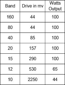
A few months ago, I acquired a TR-7 from someone on eBay and, of course, it was said to be in excellent condition. When I tested the transmitter section, I found low output on the higher bands (only 40W out on 10 meters) and sending CW for a minute or so resulted in the power out dropping to zero. A complete alignment didn't improve the situation and I began searching for a solution. I read everything published on the Web on the TR-7, and asked questions on the Drake reflector about the power output level. The general consensus was that one should be happy with 50-75 watts output on 10 meters and that "they were all that way". That wasn't a very satisfying answer, and a few knowledgeable TR-7 owners suggested that things could be better. To make a long story short, after many hours of work I was able to bring the power output up to what I considered to be a proper level, following tips from a few of the reflector members as well as using information from the Drake documentation by VE3EFJ. Since I was unable to locate a single source for all the information necessary, I've prepared this page for other TR-7 owners who might have a similar problem. The Test Setup Power measurements for this project were made with an old Bird 43 wattmeter with a 250 watt HF slug and a Heathkit oil-filled dummy load of around 49 ohms. When working on the PA "brick" outside the TR-7, the drive signal was provided by my trusty Boonton 103F signal generator which has a nice stepped attenuator and output level meter allowing you to supply an RF signal of known level into a 50 ohm load (up to 3 volts).
One nice
feature of the TR-7 is that the entire PA unit can be removed from the TR-7,
including the heat sink, so that you can work on it independently of the
TR-7. Perhaps that should have been obvious to me, but it wasn't and I
thank Garey Barrell for suggesting that approach. He told me how he had
worked on the PA using a signal generator to supply the required drive. To
do that, all you need to do is: |
||
|
|
||
|
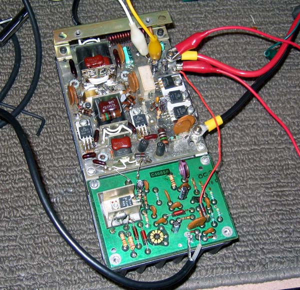
The PA unit sitting on the bench, in operation. The white and yellow leads near the top of the photo go to the ammeter to measure the "bias current". The red lead connecting the + power lead to the small post just below it sets the unit to "transmit" mode. The signal from the generator is applied via the coax seen at the bottom of the photo. |
||
|
Solving The Problem
The first
thing I did was to replace the electrolytic and tantalum capacitors on the
ALC and PA boards to eliminate those as a possible problem. There was no
benefit from that effort.
The large amount of drive required on the higher bands told me that the problem was indeed in the PA brick somewhere. Furthermore, there are back-to-back silicon diodes across the pre-driver input and the signal clipping of those diodes undoubtedly would introduce some undesirable distortion of the waveform. A scope trace of the signal coming out of the pre-driver board indeed showed a pretty ugly waveform on 10 meters. At this point, I decided to tackle the problem of the power dropping off sharply if I held the key down more than a few seconds.
In
VE3EFJ's well-known document covering Drake Mods (section 12.2, TR7 Mods and
Tech, "Late Model Driver Boards"), Wayne described a thermal runaway problem
that would produce the same symptom I was seeing. I replaced the MRF-475
transistor (no longer available from RF Parts) with one from Communications
Concepts, Inc. (http://www.communication-concepts.com/)
and inserted the resistors in the emitter lead as described by Wayne. That
provides a degenerative bias that Wayne claimed would solve the runaway
problem.
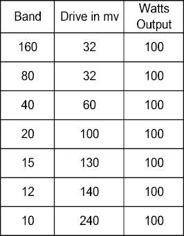
Garey
Barrell suggested that I change the final transistors to 2SC2879s as they
have higher gain at 30 MHz and so I ordered a matched pair of them from RF
Parts. I had previously installed a new pair of drivers, a matched pair of
MRF-475s from RF Parts. With the new finals, the output on the higher bands
was up quite a bit - 75 watts or so on 10 meters - but still not what it
ought to be. I then checked the bias current at the jumper position on the
PA board. While the Service Manual doesn't give a suggested bias current,
Garey said Drake suggested a value of 800 ma, but that he preferred something
closer to 200 ma. I measured 2.2 amps and something was clearly wrong.
Note that the "bias current" at that point is really the collector current
of the driver transistors - there is no bias setting capability for the
final transistors.
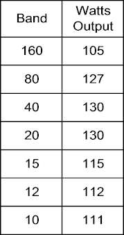
I set the ALC pot to produce 125 watts output on 20 meters with the Carrier control full CW, then switched to 10 meters and adjusted the pre-driver gain so that the ALC light just came on full. The following table shows the output power then seen on each band when adjusting the Carrier control to a point where the ALC light came on full. Current draw as seen on the power supply ammeter was 22 amps on 20 meters and 24 amps on 10 meters I'm not sure why the output on 160 meters is low and I didn't notice that while the PA was running outside of the TR-7. I assume that the power is being lost in the low pass filter section for 160. I made no attempt to see just how far the output could be increased, but when testing with the signal generator, I had no trouble driving the output up to 180-200 watts on the lower bands. I ended up with the pre-driver gain pot set to a few degrees CW past 1/2 rotation. There has been no trace of instability on any of the bands, and power output is steady in RTTY and all other modes. |
||
Based on
my experience, I'd suggest the following if you are attempting to restore
your TR-7 output level to where it should be:
Thanks to
all who made suggestions via the Drake reflector and private emails, and to
VE3EFJ, whose Drake documentation is an important part of the hobby.
|
||