Introduction: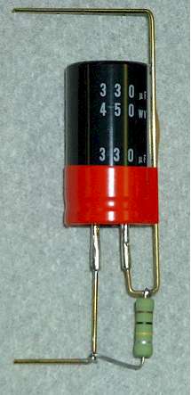
As we all know, Drake
has made some excellent ham gear over the years and I regret that they are
no longer making gear for hams. Drake enthusiasts have been keeping this
gear on the air for decades and this article is intended to foster that
objective. In spite of the excellent design of gear like the L4B and L7
linear amplifiers, age, power line transients, etc. can take their toll.
In particular, the electrolytic capacitors in the power supplies can fail
from time to time although this is not a common failure. For those in the
know, original equipment capacitors (200 mfd, 450 volt, axial leads) cost
$25 or more if and when you can find them. I’ve developed a means for
using readily available substitute (330 mfd, 450 volt, snap-in mount)
capacitors that cost under three dollars each and includes the equalizing
resistor for each capacitor. If you choose not to rewire the boards by
putting the equalizing resistor across the capacitor, then just leave the
resistor off. I’ve rebuilt one L7 power supply and will soon be doing
others. I hope this information is useful to you and that you can even
improve upon what is presented here
Materials:
-
1/16
hobby shop brass rod; one 2 1/4” long, another 5 3/4” long. Watch
out for the sharp ends of the rod! They fly some distance and are a
hazard to your eyes when cutting them with wire cutters. Always use eye
protection.
-
Non-insulated butt connectors, for 22-18 gauge wire; from Radio Shack
packet number 64-3036.
-
330 mfd, 450 v
Nichicon capacitor from All Electronics, 1-800-826-5432, $2.75 each.
-
100K, 2 watt
non-inductive resistor.
Ohmite ceramic
composition resistors, available from Digi-Key (1-800-344-4539) and is
their part #OY104K-ND
-
Electrical tape,
one roll red, one roll black.
-
3” length of Teflon
or other tubing, to fit over 1/16” brass rod.
Tools:
-
Low
wattage soldering iron, about 40 watts, solder, etc.
-
Wire cutters,
needle-nose pliers, clamps for holding small parts, etc.
Procedures:
-
Crimp one butt connector onto one end of the small
brass rod; crimp another butt connector onto one end of the larger brass
rod. Solder both butt connectors to the respective rods.
-
Take the smaller
brass rod, and make a 90 deg bend 1 1/4” as measured from the butt
connector’s soldered end, not the unused/open end.
-
Take the longer
brass rod, and make a 90 deg bend right 1/4” from where the rod exits
the soldered end of the butt connector.
-
Now the longer
brass rod is going to be “bent back on itself” to form a U shape. The
“bottom” or trough of the U, opposite what will be the open end of the
U, should be bent such that the two sides of the U are approximately
3/8” on centers. The exact dimension depends on the thickness of the
insulating tubing. If the tubing is thick, like fuel line from a hobby
shop, then the distance between the centers should be wider. Practice
on some scrap wire or brass rod to see what is appropriate for your
parts.
-
Take the insulating
tubing, and start sliding it over the non-butt connector end of the
brass rod until it comes to the trough of the U, but don’t push it any
further. This will serve as added insulation between the rod and the
case of the capacitor.
-
Take the shorter of
the two rods and slip the open end of the butt connector over the
POSITIVE (+) terminal of the capacitor. Orient it such that the bent
lead faces outward, and away from both terminals. Crimp the butt
connector to the terminal of the capacitor, and then solder it to the
terminal.
-
Take the longer
rod, and slide the open end of the butt connector over the NEGATIVE (-)
terminal of the capacitor. Orient it such that it is facing away from
the two terminals with the long dimension of the rod, with insulation,
along the length of the capacitor. Crimp the butt connector to the
terminal of the capacitor, and then solder it to the terminal.
-
Take the roll of
the BLACK electrical tape and use it to secure the insulated brass rod
to the case of the capacitor at the NON-TERMINAL end of the capacitor.
Take the roll of RED electrical tape and use it to secure the brass rod
to the TERMINAL end of the capacitor. The tape not only secures the
brass rod but also serves as an easily recognizable way of identifying
the positive and negative polarities for the respective brass rods.
-
Solder the
equalizing resistor between the two terminals such that one end is near
the 90 deg bend of the shorter brass rod and the other end is near the
trough region of the longer brass rod. Use standard procedure of
wrapping the wire lead around the brass rod, cut off the excess, and
then solder
-
Next, orient the
capacitor near the power supply board to be used as a “spacing template”
and put a 90 deg bend in the longer brass rod so it faces the same
direction as the shorter brass rod. That is, ensure both brass rods are
facing the same direction so that it will be a drop-in replacement for
the original capacitor and equalizing resistor. Note that after
bending, the center to center distance of the rods is about 4 3/8”, the
approximate distance between the brass eyelets on power supply
board. (see Figure 1)
-
The drop-in
assembly can now be inserted into the power supply board, and the brass
rods soldered to the respective eyelets. After cooling, cut off the
excess brass rod. NOTE that the cut off ends of the rod will be sharp
and fly some distance when you cut them off! Always wear eye
protection.
This method will save
quite a bit of money over the standard equipment, axial lead electrolytics
that sell for about $25 each, if and when you can find them. Note, if
your supply is an early vintage with 600 ma rectifiers, it might be a good
idea to upgrade them due to the higher capacity and surge current of the
newer caps. I used 3A 1 kv diodes.
Enjoy those Drakes!
73,
Evan
|