Drake Home Page       Drake Technical Tips Menu

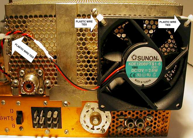
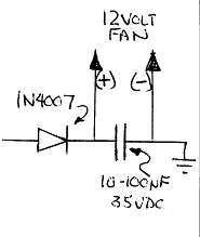
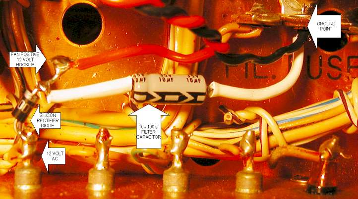
T-4X OR TR-4 DC FAN INSTALLATION

By: Mark Gilger / WB0IQK

 The following fan installation can be performed on either T4X – TR4 series radios. No holes need to be drilled. The fan is installed to pull air out of the cabinet. Plastic Tie Wraps are used to secure the fan to the PA stage.  A simple half wave bridge rectifier circuit is installed to power a 12 volt DC fan. These fans can be located at any hamfest or computer show. They are used in PC’s for cooling.


  • As viewed from the front of the radio, bottom side, locate the first feed through located on the side of the power amplifier stage. This is the 12 volt AC filament supply.

  • Cut both lead of the diode to ½ inches.

  • Solder the non banded end of a 1N4007, or equivalent diode to the 12 volt filament feed through, as seen below.

  • Bend a small hook in the banded side of the diode. This will be used in solder the capacitor and positive fan lead.
  • Solder the positive end of a 10uf capacitor to the banded end of the diode installed above. The value of the capacitor, except for it’s voltage rating, is not critical. The higher the capacitor value, the higher the voltage supplied to the fan. When I used a 10uf capacitor, I had 8 volts feeding the fan. In this configuration, the fan runs slower and is much quieter. If you need higher voltage for your fan, raise the value first to 100uf or greater.  I’ve used 1000uf to power a 24 volt fan with no problems. Be sure to use heat shrink on the longer capacitor leads to prevent shorts to nearby components.
  • Solder the negative end of this capacitor to a nearby ground lug. I used the center lug on the filament fuse terminal strip, which is grounded to the chassis at that point.

  • Feed through two lengths of wire, one red and the other black, to the location where the half wave bridge rectifier is mounted. There are several holes near the mounting location to feed the wires up into the upper part of the chassis. Do not feed them through the PA stage where the 6JB6 finals are located.

  • Solder the red lead to the positive end of the capacitor hooked to the banded end of the rectifier diode.

  • Solder the black lead to the same point you solder the negative capacitor lead to.

  • Solder the red and black leads to the appropriate fan leads.