Drake Home Page Drake Technical Tips Menu
![]()
|
Installing New Replacement SSB Filters In A Drake TR-4CW Transceiver By Jeff Covelli / WA8SAJ - wa8saj@ncweb.com The Drake TR-4 series radios have been around since the mid 60’s and they have been very good to many folks that own them. Once in awhile one of the two SSB filters decides to fall off frequency or just plain drop in signal level, and your left with a radio that is virtually useless. Now if you can find a single band with the correct sideband that works, this is fine, but the rest of the bands will not follow with a bad filter and here is why. A review of the Drake TR-4 series filter scheme. First is uses a 9.0 MHZ system, very common in those days. There is one 9.0 MHZ carrier oscillator and two SSB filters “lower” and “upper” vs. two carrier oscillators and one SSB filter, used in other rigs. The reason there are two filters, there is no problem having to move the VFO to compensate for the sideband, when changing from lower to upper SSB, your always centered in the pass-band. The TR-4 uses a VFO frequency of 5.0 to 5.5 MHZ, so on 80 meters the mix is direct, (vfo of 5.0 MHZ plus 4.0 MHZ on 80 meters) = 9.0 MHZ I.F. and the “lower” sideband is used like normal. Now on 20 meters (14.0 MHZ on 20 meters minus the vfo of 5.0 MHZ) = 9.0 MHZ and since the mix is reversed, the sideband filter has to change to allow the “upper” sideband to pass. This is why when going from band-to-band you see the sideband filter lights changing and the operator has to make sure that the correct sideband is selected for each band. It is confusing, there is more in the technical aspect of the TR-4, but I think you will get the picture of how the mixing is done and why the filters get switched around.
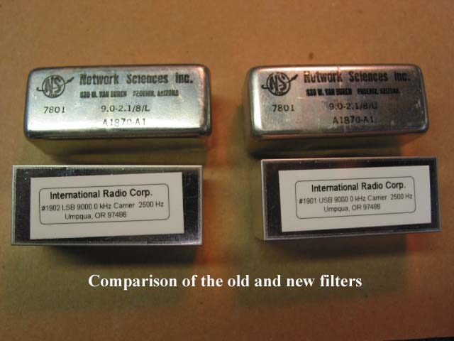
I had asked George from International Radio Corporation (INRAD) if it was possible to make new SSB filters for the TR-4 series radios. He had not had enough requests at the time to make filters, but one day I finally sent him a couple of filters from an old TR-4 I had laying around. He swept them on his “tracking generator” and went to work on having some made and I was able to get started on replacing both of my filters in one of the TR-4CW’s I have here. I used the same radio that I had for the A. M. filter, since it was working so well, I could get a good feel how the filters would work, well I can say they work very well. With that being said, the folks that need to save their prized TR-4’s have a way of reviving the rig like new! The first thing I did, was to sweep the original filters using an audio signal generator into the microphone jack and watching the pass-band of the existing filters as I went from 300 HZ to about 2100 HZ. There was a drop of about 3 DB on some of the frequencies on both sidebands across the spread. The 9.0 MHZ frequency range for sideband filters are very hard to get a perfect ripple of plus or minus ½ DB like a 455 KHZ mechanical filter as used in a Collins KWM-2 or even a 5.0 MHZ filter on a Drake T-4XC, etc.
|