|
Drake Home Page Drake Technical Tips Menu
|
|
Drake TR-7 A.M. Transmit Filter Modification
Page 1 >Page
2< Page 3 |
| Getting Started: Get yourself a muffin pan or small containers to put all your separate screws that will come off during this project! Taking the cover off the TR-7 is easy, just slide the cover off after removing the eight machine screws from the bottom. Next you will take off the bottom cover after removing the sheet-metal screws. The top of the radio is where you start, since the “store” switch and the lamp have to be wired first, then to the bottom of the TR-7 and the mother-board. |
| NOTE: You may not need to remove the DR-7 digital-board if
the following is done this way. 1) With the back of the TR-7 towards you, start this way first. 2) Remove the existing wires from the “store” switch; these will not be used for this project.
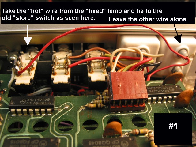
3) The hot wire from the “fixed” lamp can be cut closest to the xmit “fixed” switch. Now solder the cut wire to the “store” switch (see photo #1). If the cut wire is too short, you might have to extend it. Note: The other wire on the “fixed” lamp goes to ground already.
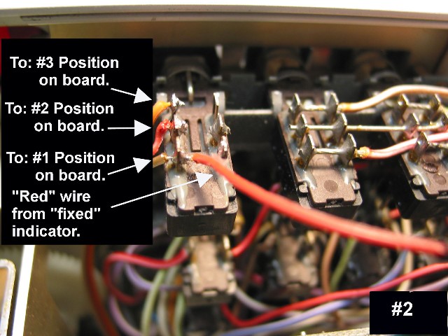
4) Take three wires (ribbon-wire works great) and solder them to the
“store” switch (see photo #2). 5) Now turn the TR-7 with the front panel towards you. 6) The three wires are now run down to the bottom mother-board and soldered to their connections as seen in the photo. Note: Make sure you take notice of what #position you are applying the wires to, very important!
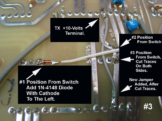
7) As seen in the (photo #3) follow the directions as to cutting the
traces both sides of the #3 position and adding the jumper, then
adding the one diode in series (note direction of diode) with the #1
position. 8) Install the rest of the remaining wires coming from the “store”
switch for #2 and #3 position. |