Drake Home Page       Drake Technical Tips Menu

Drake TR-7 A.M. Transmit Filter Modification

Page 1    Page 2   >Page 3<

By: Jeff Covelli WA8SAJ
5368 Melody lane
Willoughby, Oh 44094
wa8saj@ncweb.com

Getting Started:  Continued

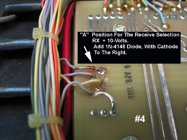
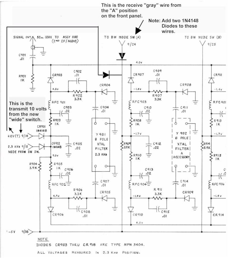
9) The “RX” 10-volt line (top gray wire) on the left of the mother-board has a diode added in series with it (note direction of diode). This is the ”A” position on the front-panel selection (see photo #4).


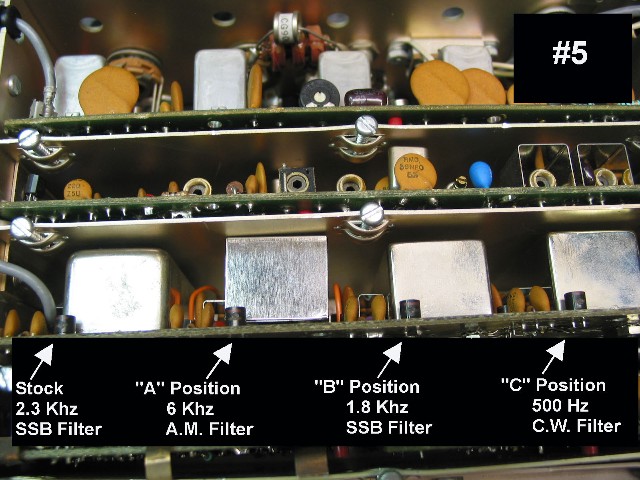
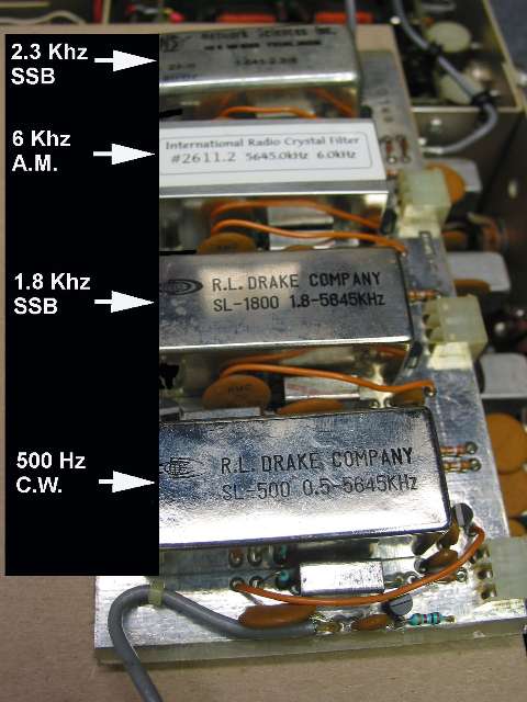
10) Mount the 6 Khz A.M. filter in the “A” position only (see photo #5) on the I.F. filter board. Note: You can try and find a used 6 Khz A.M. filter or get a new one from INRAD PO Box 2110, Aptos, CA 95001 USA. New phone number is (831) 462-5511. The e-mail is:sales@inrad.net. WEB page is:www.qth.com/inrad/
 

11) Now this completes the wiring of the TR-7!


How To Operate:

When you operate on A.M. with the TR-7, first make your filter selection in the “A” position for receive. The old “store” switch is now pushed in for the “W I D E” transmit, and the old “fixed” lamp will light when you transmit. The carrier should be set for no more than 25 watts for any length of time and bring the microphone gain up until the watt-meter starts to wiggle upward on voice peaks. I recommend a stock D-104 (no pre-amp) and solder the microphone audio “hot” lead to pin #4 of the microphone connector. Drake has already installed the 680 K ohm resistor; which is in series now with the microphone element and makes the D-104 sound great! Have fun with the Drake TR-7 and enjoy A.M. with a great rig.


Pictured below is the wiring diagram showing the wiring changes for this modification.


Next Page    Previous Page