WB4HFN Home Page Drake Technical Tips Menu Drake Home Page Collins Home Page Heathkit Home page
![]()
Drake L4B - All In One Redesign
by: Ronald Baker / WB4HFN
Contents Page 1 Page 2 >Page 3< Page 4
![]()
|
Input Circuit Redesign
I never knew why Drake used this style of feed-through
capacitor but I knew they needed to go. Those capacitors along with
the large bifilar choke isolates the RF input power from the ground potential
through the filament power transformer. The bifilar choke is
attached to the first tube socket. The tube filaments are in parallel so I just
cut the leads going over to the second tube when I removed the rear tube socket.
Shown in the second picture to the left is a close-up of the remaining tube
socket. The original bifilar choke is attached to the first tube socket
which was left in place. You can see along the bottom of the
socket where the copper strapping was cut at the tube pins going to the second
tube socket that was removed. I also added that disc capacitor to
make sure the RF drive was equally distributed across both sides of the
I decided to remove the large feed through capacitors and add smaller disk capacitors of the same value to both sides of the circuit to ground. I also added the same value capacitor across both lines to ensure any stray RF signal was eliminated at this point. The basic function of this circuit is to pass the filament voltage to the tubes and completely isolate the RF input signal from the ground potential through the power transformer. The input power from the exciter is routed through the antenna relay directly to the tube filaments. The L4B design is "grounded grid", so in this case the input power is applied to the tube filaments since there is no separate cathode. Shown in the picture below is the feed-through capacitor resign.
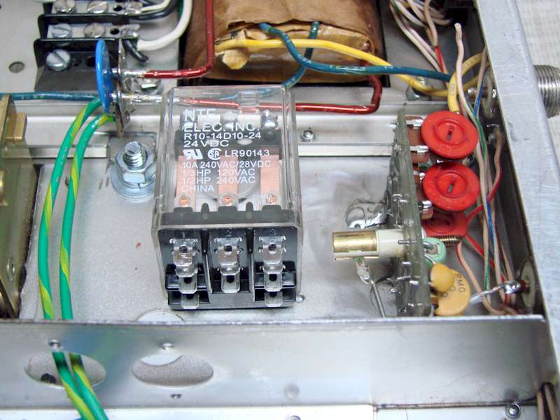
Shown the pictures at the bottom, on the left, is the new antenna relay mounted and the watt meter board turned 90 degrees and remounted parallel with the chassis rear. Remounting this board this way gives easy access the the red watt meter calibration controls and puts it directly in front of the RF input and output connectors. The other picture at the bottom, on the right, shows the "before modification", how the original relay and watt meter board are mounted in the L4B Amplifier. Also, note the large feed through capacitors in the filament circuit were removed in the modified L4B design to make room for the new larger antenna switching relay.
|
||
|
The picture above is the modification with the new sealed relay and repositioned watt meter board. |
The picture above is the original L4B design with the open frame relay and large feed through capacitors. |
|
|
|
||
 When considering the underside chassis
component layout I wanted to keep as much of the wiring original as
possible. I also wanted to replace the antenna relay with a
new sealed relay. The new relay is about 50 percent bigger than the
original relay, so mounting the relay
where
I could get to the soldering terminals became my first issue.
I quickly came to the realization I would need to move some of the components around or eliminate then to allow for the needed
relay space. Along the back where the original relay
was located seemed to be the best spot since it was directly in line with both
the RF input and output connectors. The only problem with that space was the watt meter board and the
two large feed-through capacitors in the filament circuit were both in the way.
When considering the underside chassis
component layout I wanted to keep as much of the wiring original as
possible. I also wanted to replace the antenna relay with a
new sealed relay. The new relay is about 50 percent bigger than the
original relay, so mounting the relay
where
I could get to the soldering terminals became my first issue.
I quickly came to the realization I would need to move some of the components around or eliminate then to allow for the needed
relay space. Along the back where the original relay
was located seemed to be the best spot since it was directly in line with both
the RF input and output connectors. The only problem with that space was the watt meter board and the
two large feed-through capacitors in the filament circuit were both in the way.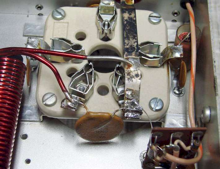 tube
filaments.
tube
filaments. You can see the blue disk capacitors on the left going to
ground from each side of the transformer and on the right the single
blue disk capacitor going across the two leads from the bifilar choke.
This configuration provides the additional space for the relay, however, with
the watt meter board in the same area still makes it a tight fit. The watt meter board runs
perpendicular to the rear panel. By turning that board 90 degrees in the
same area provide plenty of room to mount the new antenna relay and
access the contacts for wiring.
You can see the blue disk capacitors on the left going to
ground from each side of the transformer and on the right the single
blue disk capacitor going across the two leads from the bifilar choke.
This configuration provides the additional space for the relay, however, with
the watt meter board in the same area still makes it a tight fit. The watt meter board runs
perpendicular to the rear panel. By turning that board 90 degrees in the
same area provide plenty of room to mount the new antenna relay and
access the contacts for wiring.