WB4HFN Home Page Drake Technical Tips Menu Drake Home Page Collins Home Page Heathkit Home page
![]()
Drake L4B - All In One Redesign
by: Ronald Baker / WB4HFN
Contents Page 1 Page 2 Page 3 Page 4
![]()
|
Amplifier Metering And Cooling Functions
The L4B Amplifier metering functions were
basically kept the same as the original design, but a few components needed to be
moved around. The plate current meter function was left
unchanged, but now that only one tube is being used the
The picture to the above left shows the resistor divider network soldered to the base of the plate choke. The picture on the right shows the resistor divider network placed between the high voltage and filament transformers and plate tuning capacitor and output loading coil. The other end of the resistor divider network is soldered to a terminal strip and held in place by both ends of the soldered connections. The clear plastic tube holding the resistor network is fairly thick and insulates the resistors so they can be placed close to the chassis and other components without fear of arcing.
The original cooling fan design in the L4B was a 90 degree squirrel cage fan blowing air under the chassis through a channel and up through the tube sockets. The air pressure would blow up through the tube socket and around the tube and exit through the top of the chimney. This concept worked well for cooling but the blower was noisy and took up a large area of the chassis. For the redesigned L4B this blower was the first item to be removed in order to make room for the high voltage transformer. The redesign made the L4B a very compact with no room for that big blower. Also since there was only one tube in the amplifier less cooling would be needed. The direct air flow method of cooling seemed to be the most practical method. Since several other amplifiers such as the Collins 30L1 and the Heathkit SB-200 and SB-220 used the same type of cooling, this proved to be an acceptable cooling method.
In the L4B redesign I found the open
area between the final tube and the plate tuning capacitor was the best location
for the fan. There was just enough room to locate a small 5 inch
muffin fan with enough room on all sides so it would not interfere with the other
components. Mounting
The picture above right shows the fan assembly mounted to the chassis and to the right side of the final tube. The fan blows across and around the tube and exhausts out the left side of the amplifier. The picture to the right is another view of the fan and how it was mounted to the chassis.
|
|
|
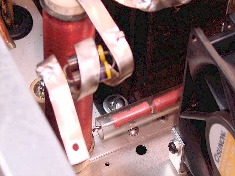 plate current meter calibration
changed, so that needed to be recalibrated. The calibration
control, white control just below the meters, has plenty of range so no component
changes were needed. The power supply voltage
metering required some component relocation since the high voltage divider
resistor network was located down the left side of the plate tuning capacitor,
which is now where the cooling fan is placed. The high voltage
resistor divider network consists of four 10 meg-ohm resistors inside a plastic
tube which runs parallel along the left side
of the plate tuning capacitor. The final tube plate isolation choke
was moved slightly back from the original position. That choke is now
directly in line
with a small 3/4" wide gap between the front edge of the high voltage transformer and the
rear of the plate tuning capacitor and the rear side of the fan. The resistor divider
network fits nicely down is this narrow space which can be seen in the second
picture below. One end of the resistor divider network
is soldered to the base of the plate choke to sample the plate voltage.
The divider network slides down in that narrow open slot and is attached on the
other end to a terminal strip just in front of the filament transformer.
The wire from the low side of the resistor divider network goes under the
chassis back to the meter function switch.
plate current meter calibration
changed, so that needed to be recalibrated. The calibration
control, white control just below the meters, has plenty of range so no component
changes were needed. The power supply voltage
metering required some component relocation since the high voltage divider
resistor network was located down the left side of the plate tuning capacitor,
which is now where the cooling fan is placed. The high voltage
resistor divider network consists of four 10 meg-ohm resistors inside a plastic
tube which runs parallel along the left side
of the plate tuning capacitor. The final tube plate isolation choke
was moved slightly back from the original position. That choke is now
directly in line
with a small 3/4" wide gap between the front edge of the high voltage transformer and the
rear of the plate tuning capacitor and the rear side of the fan. The resistor divider
network fits nicely down is this narrow space which can be seen in the second
picture below. One end of the resistor divider network
is soldered to the base of the plate choke to sample the plate voltage.
The divider network slides down in that narrow open slot and is attached on the
other end to a terminal strip just in front of the filament transformer.
The wire from the low side of the resistor divider network goes under the
chassis back to the meter function switch.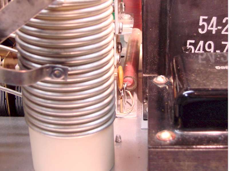
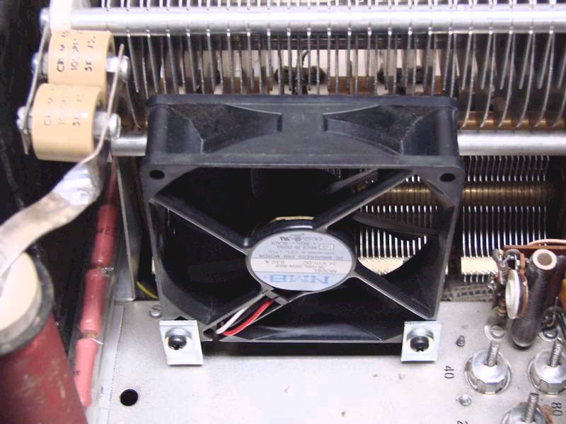
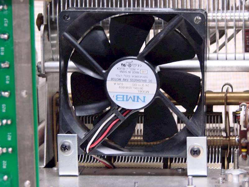 the
fan was accomplished with a one inch 90 degree bracket bolted to both sides of
the fan and to the chassis. I choose a 12VDC fan which I wired to a 12 volt low
voltage power supply under the chassis and wired in for continuous operation.
the
fan was accomplished with a one inch 90 degree bracket bolted to both sides of
the fan and to the chassis. I choose a 12VDC fan which I wired to a 12 volt low
voltage power supply under the chassis and wired in for continuous operation.