WB4HFN Home Page Drake Technical Tips Menu Drake Home Page Collins Home Page Heathkit Home page
![]()
Drake L4B - All In One Redesign
by: Ronald Baker / WB4HFN
Contents Page 1 Page 2 Page 3 Page 4
![]()
|
The New High Voltage Circuit Board
From the beginning
my plan for the high voltage board was to install one of these newly designed
upgrade board on the market. I had thought about doing regular hand wiring
but mounting all the filter capacitors and other components became a legalistic
problem with the limited space above and below the chassis. There are a
couple of sources for the upgrade kit for the L4PS power supply.
This is a single board which contains all the high voltage components neatly
arranged in a compact package. I choose to use the Heathkit
Shop upgrade kit because their board is made with a high
In the picture to the left shows the Heathkit Shop board completely assembled and ready to install. You will notice that each filter capacitor and rectifier has equalizing resistors. The board layout is very nice and neat, and the board is labeled very well to minimize mistakes being made. At first I wasn't quite sure how I would mount the board, but quickly concluded it needed to be mounted on top side of the chassis. I found that I had three options for mounting. I could side mount the board vertically on the right or left side towards the rear. The third option, which I ruled out quickly was to suspend the board on stilts placing the board along the top of the amplifier just under the case top. I quickly realized this would be a night-mare from a mounting and cooling prospective. Mounting the board on the left side provided very little clearance between the filament transformer. I found the right side towards the rear worked the best. There was plenty of room to mount the board and plenty of clearance to prevent arcing to the chassis or other components in the same area. The board was now close enough to the power transformer so the leads reached the board without extending them, and only a couple of inches to reach the high voltage isolation choke supplying the voltage to the tube plate circuit.
In the pictures below are a couple of
different angles showing how the high voltage board was mounted. As you
can see there is plenty of clearance from the other components to prevent
arcing, and the transformer and high voltage plate choke and still close enough to make
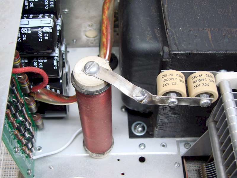
the connections to them very short. You will also notice in the
picture on the left where I fabricated a bracket to mount the high voltage
blocking capacitors to the plate tuning capacitor and attaching to the top of
the plate choke.
The picture below shows
how the board was mounted to the chassis. In each corner of
the board there are mounting holes which I used to attach the board to the side
of the chassis. The board was mounted inside the top
side rail about a 1/4" down from the top and along the backside of the
chassis. I used 3/8" metal stand-offs to keep the board away
Mounting the high voltage board in this position turned out to be the best possible location. It is back far enough so that it does not interfere with the cooling fan air flow and has plenty of room for the heat generated from the board itself to escape and has enough clearance to prevent arcing and keeping all the connecting leads fairly short.
|
|
|
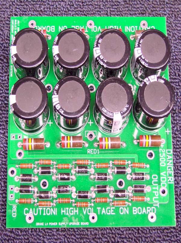 quality
epoxy board and it includes equalization resistors across the filter capacitors and
rectifiers.
quality
epoxy board and it includes equalization resistors across the filter capacitors and
rectifiers.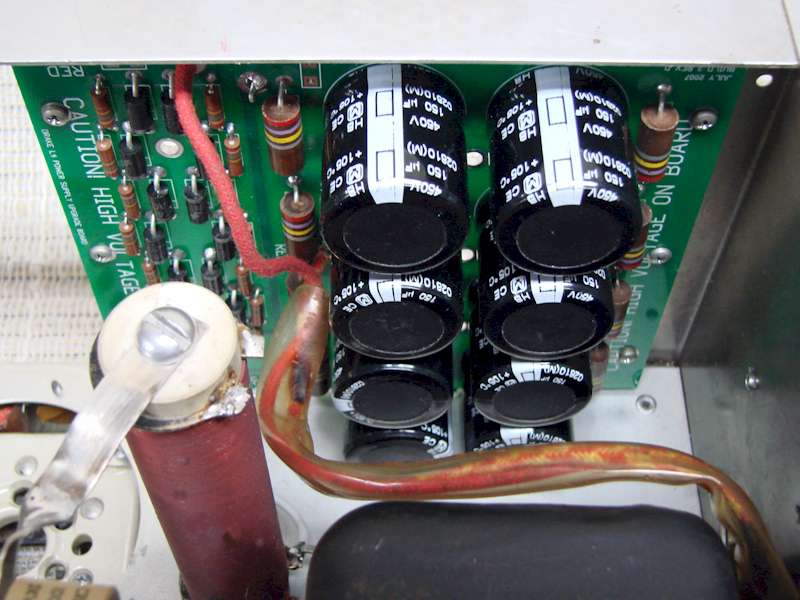
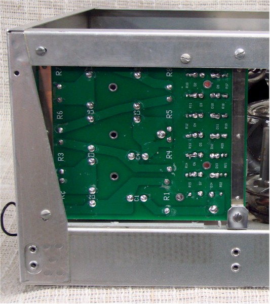 from
the chassis to prevent arcing, and to provide a solid ground connection to the
board in all four corners. Along the bottom of the board I mount the
board to the rear vertical chassis support just like I did at the top.
The lower front of the board there was nothing to mount that corner to.
Initially I was going to leave that corner hanging and it would have been
stable, but I decided to fabricate a small "L" shape bracket, mounting it to the
chassis to hold that corner of the board in place.
from
the chassis to prevent arcing, and to provide a solid ground connection to the
board in all four corners. Along the bottom of the board I mount the
board to the rear vertical chassis support just like I did at the top.
The lower front of the board there was nothing to mount that corner to.
Initially I was going to leave that corner hanging and it would have been
stable, but I decided to fabricate a small "L" shape bracket, mounting it to the
chassis to hold that corner of the board in place.