WB4HFN Home Page Drake Technical Tips Menu Drake Home Page Collins Home Page Heathkit Home page
![]()
Drake L4B - All In One Redesign
by: Ronald Baker / WB4HFN
Contents Page 1 Page 2 Page 3 >Page 4<
![]()
|
Chassis
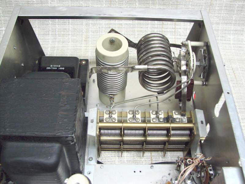
Reassembly Installing the Output Tuning Components After the high voltage transformer was mounted the next step was to remount the output tank components and other hardware that was going to be reused. First I remounted the loading capacitor and the tank coil and band switch. As you can see in the picture on the left the transformer placement was critical leaving only a small amount of clearance between the output tuning network. Both of the large coils in the tank circuit are silver plated. Over the years those became tarnished. Before reinstalling them I did some cleaning making them shiny and looking like new again.
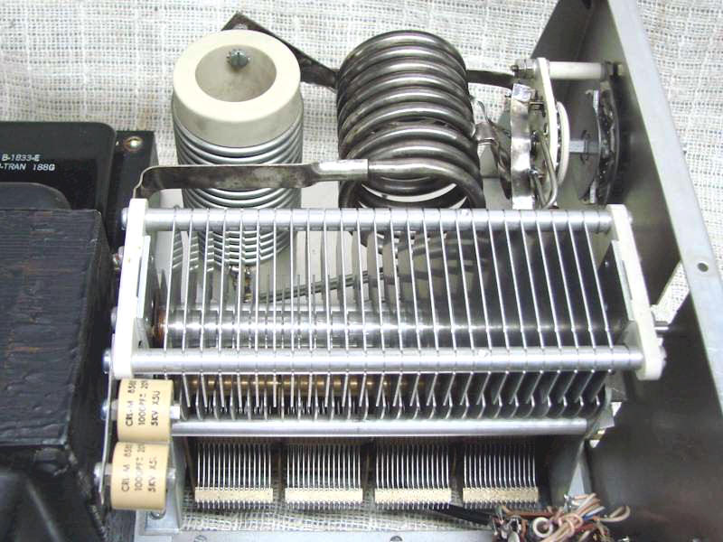
In this picture the plate tuning capacitor is mounted and connected into the circuit. Also mounted to the tuning capacitor are two door knob coupling capacitors going to the final tube plate. I had to make a small bracket to mount those capacitors to keep them far enough away from the transformer to prevent arcing. There is roughly 3/4 of an inch clearance which is enough room to not interfere with the tuning or the 2800VDC from arcing to the transformer.
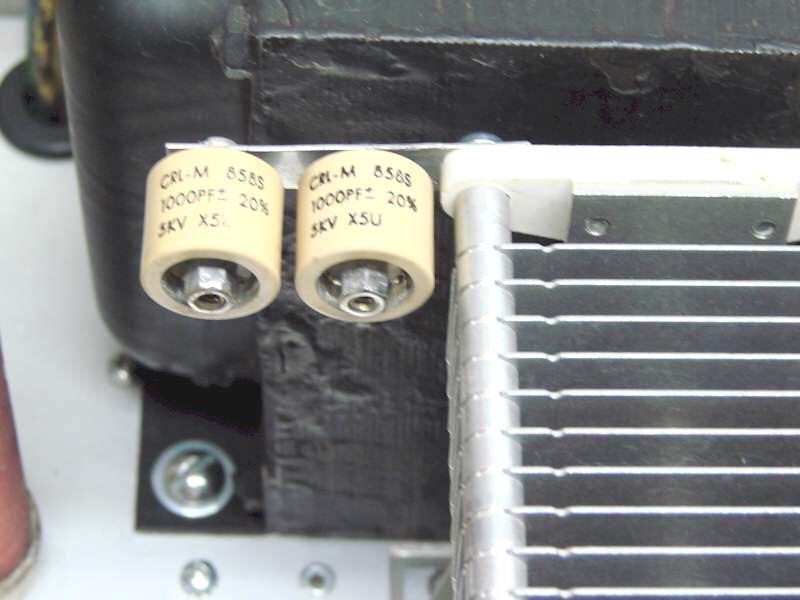
Shown in the smaller picture on the right is a close-up vies of how the door knob capacitors were mounted to the plate tuning capacitor.
Next I reassembled the front panel components.
First I put back the two meters and wired them into the circuit, Next I
installed a modified Standby/AGC switch, the switch drive Remember I said
earlier I mounted a slightly modified Standby/AGC switch.
In the L4PS power supply there is a 5K ohm, 10 watt resistor
that is a common failure in the power supply. When it goes bad, the resistor opens up, which takes
away the ground potential for the high voltage filter
capacitors. That in turn puts high voltage on the AGC control
which immediately
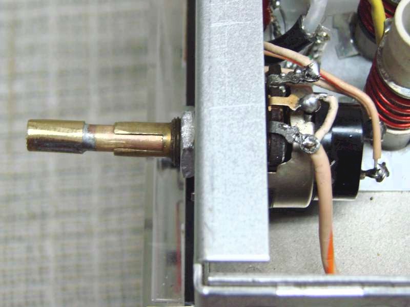
Looking through my junk box of controls I found a control out of an old Heathkit HW104 which was the right resistance value, a pull switch, and had a long shaft. The problem was the control was a dual control pot and the control section I needed was attached to the off/on switch and the inner shaft which is to small to attach a Drake bar knob. To make long story short, I cut off the outer shaft so it stays behind the front panel. The inner smaller diameter shaft is now long enough to stick through the front panel but not the right diameter to mount the knob. To make the inner shaft the right diameter for the knob I soldered the outer shaft piece I cut off to the end of the smaller inner shaft. So now with the outer shaft cut off and hidden behind the front panel, the inner shaft is the right length and size to extend out from the front panel and mount the proper Drake knob. From the front of the amplifier you can not tell it from the original control. Shown in the picture on the left is that AGC/Standby control showing the modification I made. |
|
|
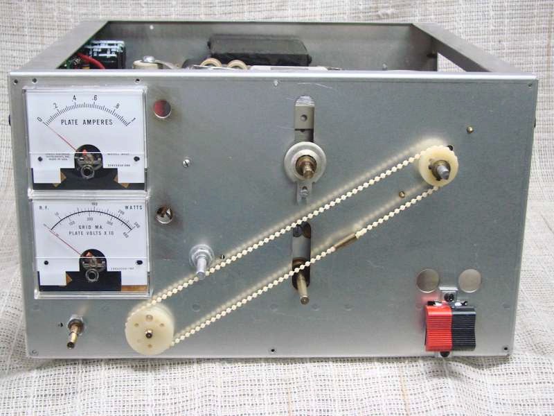 chain
and the power switches. There is a short story about the power switches.
When I got the L4B chassis the switches were both white and definitely not the
right type. The red and black power switch assembly is rare and hard
to find. E-bay.com is usually a good
resource for parts. Knowing I would be needing a new switch
assembly I watched e-Bay for several weeks with no luck. The day
came when I needed to mount the power switch and was going to use the old white switches
I had,
an original switch appears on e-Bay.com. Well this switch was critical
for keeping the amplifier looking original. Well I won that auction but that
switch assembly cost me $125.00, plus shipping. Yes, I cried a
little, but knew it was essential to keeping the amplifier original looking.
chain
and the power switches. There is a short story about the power switches.
When I got the L4B chassis the switches were both white and definitely not the
right type. The red and black power switch assembly is rare and hard
to find. E-bay.com is usually a good
resource for parts. Knowing I would be needing a new switch
assembly I watched e-Bay for several weeks with no luck. The day
came when I needed to mount the power switch and was going to use the old white switches
I had,
an original switch appears on e-Bay.com. Well this switch was critical
for keeping the amplifier looking original. Well I won that auction but that
switch assembly cost me $125.00, plus shipping. Yes, I cried a
little, but knew it was essential to keeping the amplifier original looking.
 burns
the control open.
It only takes a few seconds for the control to be destroyed.
This is another component in the L4B that is very hard to find,
and the chassis I acquired the control was bad.
burns
the control open.
It only takes a few seconds for the control to be destroyed.
This is another component in the L4B that is very hard to find,
and the chassis I acquired the control was bad.