|
Inside The Drake TR-7
Transceiver
by: Ronald Baker / WB4HFN
Contents
>Page 1< Page 2
Page 3 Page 4
Page 5 Page 6
Page 7
Page 8
Page
9
Page 10
Page 11
Page 12
Page 13
Page 14
Page 15
Page 16

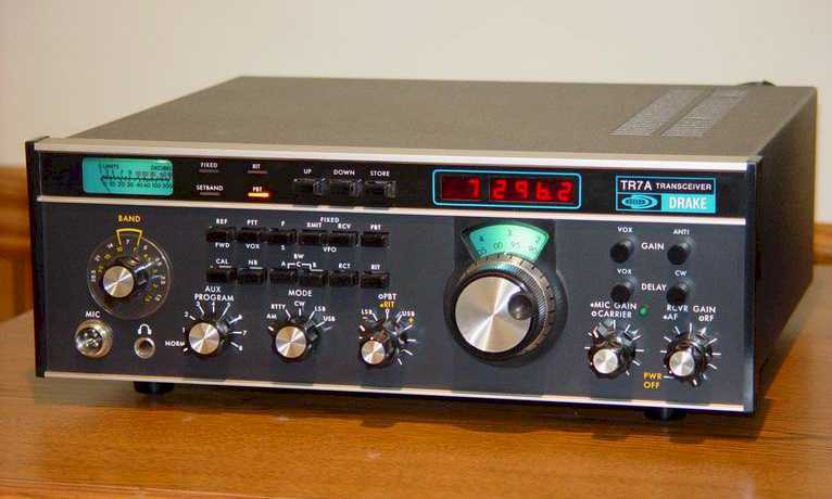
| The Drake TR-7 Transceiver, designed by
the R.L. Drake Company was considered the first all solid state
commercially available transceivers.
Being 100% solid state all the circuits were broadbanded so
there was no need for preselector tuning or transmitter
adjustments across the entire 1.5Mhz to 30Mhz operating range of
the transceiver. The high performance frequency
synthesizer and the Drake designed PTO provided smooth tuning
with a 1Khz analog dial and 100Hz digital readout. The
frequency synthesizer provided tuning ranges in 500Khz steps
across the operating range of the transceiver selectable with
the Band Switch and the "UP" and "DOWN" front panel pushbuttons.
Drake was the first to introduce "Up-Conversion" for Amateur
Radio transceivers. This was the process
putting the 1st IF above the received frequency.
Drake put the 1st IF at 48.05Mhz placing image frequencies well
outside the tuning range of the receiver. The
transmitter was designed to operate at 250 watts input power
across the entire operating range of the radio. This
netted a typical output power level between 130 and 150 watts on
the lower bands and 90 and 100 watts on 15 and 10 meters.
The transmitter being all solid state and designed to produce a
flat frequency response across the entire operating range
required no transmitter tuning or adjustment. The transmitter included VSWR protection which shut-down
the power level when the antenna was not properly matched. |
| In the hay-days of Drake before the
death of Bob Drake there was much discussion among the
engineers on the TR-7. The discussions were on
whether the new design should be a tube design, possibly a hybrid design, or forge into the new
world of solid state. The more seasoned
engineering leaned towards using the "tried & true" tube
design. However, after the smoke cleared the younger
college grad engineers won the debate for an all solid-state
design. During the next couple of year the
TR7 design went through several development phases and
sometimes into yet uncharted waters. Along the
way there were many all nighters, bar-room discussions,
ruffled feathers, and impeded territories, but it all
eventually came together. During it all, the
Drake engineers overcame some insurmountable obstacles like
the BFO signal that could be heard a block away until they
realized the metal shield was acting like an antenna, or the
power amplifier that self-destructed itself with design
changes and a little SWR. |
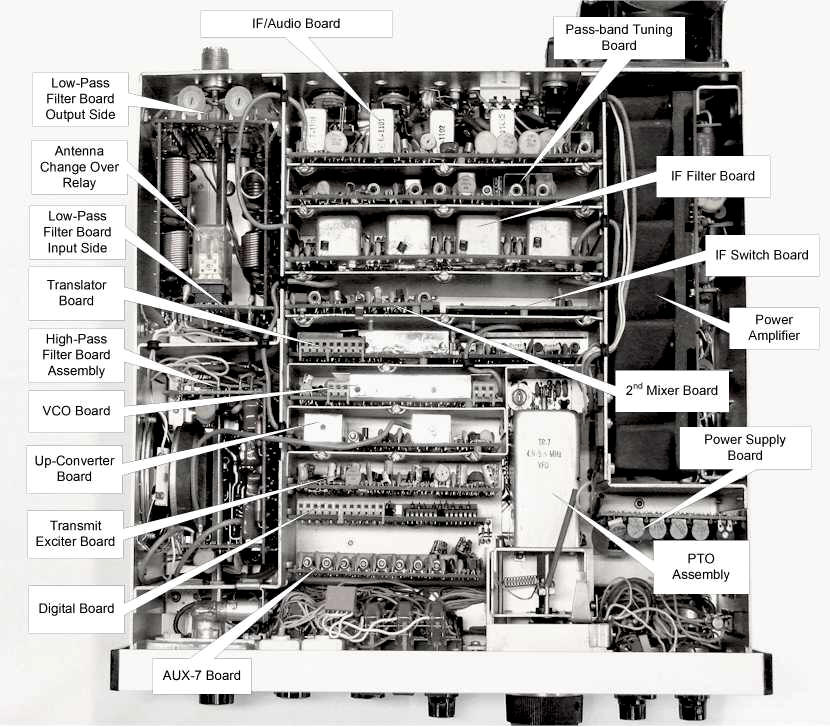
The TR-7 Board Layout
| The basic layout of the TR-7
Transceiver is a modular design. Each
section of the transceiver was built on individual circuit
boards that plug into a mother board which Drake refers to
as the Parent Board. The Parent Board was
connectorized to except the smaller circuit boards and
interconnect the boards carrying power, switching voltages
and low frequency signals between the boards.
The high frequency signals used small plug-in coax cables on
the top side of the transceiver running between the circuit
boards. The picture below shows the placement of
each board and other major components in the transceiver.
You can also see the small coax cables interconnecting the
individual circuit boards. |
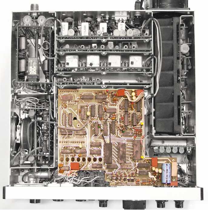
| When the TR-7 Transceiver was first
introduced, the Digital Display Board was an add-on option.
After several months of production the digital display
became a standard feature with all transceivers.
As shown in the picture below, the digital display board
mounted over the top of several circuit boards in the front half of the
transceiver. The Digital Display Board also had
connectors on the bottom side that plugged into the top
side of the Digital Board, VCO Board and Translator Board.
On the top side of the Digital Display Board there are several small connectors
for power and front panel
switches. The Digital Display Board had a series
of eight holes across the front which was to access the
channel trim capacitors on the AUX-7 Board.
On the back of the Transceiver there is a switch labeled
"Normal - Ext" and a plug-in connector directly under the
switch. In the "Normal" position the
Digital Display showed the operating frequency of the
transceiver. In the "Ext" position the Digital Display
Board became an external frequency counter good to 150Mhz.
The input connector for the frequency counter function was
directly below the switch on the rear panel. |
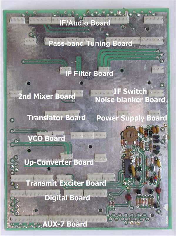
The Parent Board
| The Parent Board, is the
transceiver's mother board on which all the other smaller
individual circuit board plug into. Detailed below, each of the
smaller boards has a particular place where they plug into
the mother board. The mother board
provides most of the interconnections between the smaller
boards including switch and unswitched power, control
voltages and signaling. Most of the critical RF
signals are interconnected with separate coax cables from
board to board. All the front panel
controls and functions and the rear panel connectors all
connect to the Parent Board along the front and rear
edges of the board. The only active circuits on
the Parent Board is shown in the bottom left corner in the
picture. That circuit controls the RIT offset
tuning, the PTO switching between transmit and receive and
external devices such as the RV-7 remote VFO. |
Next Page
Previous Page
|