|
Inside The Drake TR-7
Transceiver
by: Ronald Baker / WB4HFN
Contents
Page 1 Page 2
Page 3 Page 4
Page 5 Page 6
Page 7
Page 8
Page
9
Page 10
Page 11
>Page 12<
Page 13
Page 14
Page 15
Page 16

Replacing The Internal Fuse
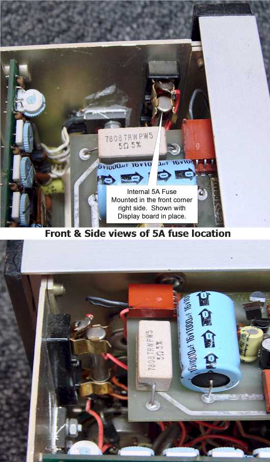
The Drake TR-7 Transceiver does have one internal 5
amp fuse. The fuse is a standard AG3 fuse, 5 AMP rating. This
is the first place you should check if the radio is totally dead and you
know the connected power supply is delivering the proper voltage.
To locate the fuse first removing the top cover.
The fuse holder is mounted on the right side panel in the front-right
corner of the radio just beyond the edge of the Digital Display Board
and directly in front of the Power Supply Board.
Before attempting to remove the fuse make sure all
power is disconnected from the radio. The fuse is somewhat hard to access but with care
and a small flat blade screwdriver the fuse will easily pop out from the
holder. Replacing the fuse is a bit more tricky. First
center the fuse over the holder clamps then push into place.
Access to the fuse is easier if you work from the long side, going in
behind the Digital Display Board.
Use extreme case when replacing the fuse you do not
touch or move the small blue controls on the power supply board,
especially the +10VDC regulator adjustment, the first control mounted
up-right closest to the outside case edge. Moving these controls
could put the transceiver out of alignment and/or voltage regulation.
Replacing The Dial Lamps
| The Drake TR-7
Transceiver has two replaceable dial lamps, one behind the
S-Meter and the other behind the VFO analog frequency
readout dial. The bulb is a standard #53 bulbs
rated at 12VDC, replacing them ranges the two extremes,
"Simple and Easy", to "Your Worst Night-mare".
The bulb behind the "S-Meter" is the quick and easy
choice, the bulb socket clamps to a bracket directly behind
the meter. The socket assembly just lifts off
the bracket by pulling upwards on the assembly to snap in a
new bulb. |
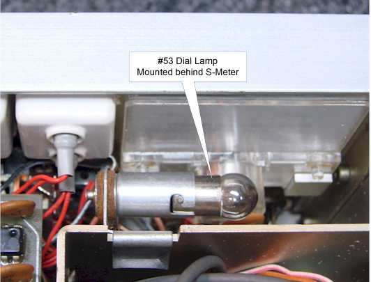
|
The picture above shows
its mounting directly behind the S-Meter easily accessible
once the case top is removed. |
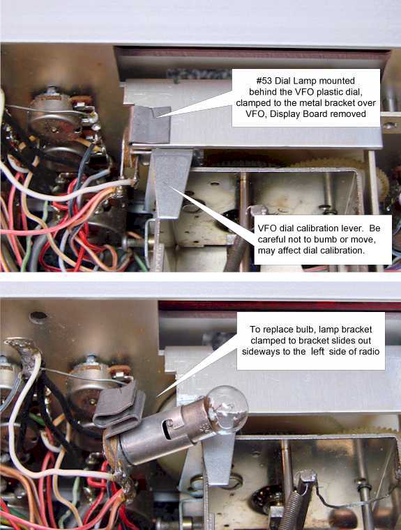
|
Pictured above in the top picture shows the location of the
dial light bulb behind the VFO dials. The second
picture shows the bulb socket assembly removed by pulling
sideways to the left.
|
|
Replacing the bulb behind the analog VFO
dial by some would be considered a "night-mare" just getting
to it. After removing the wrap-around case your
first task it to remove the top mounted Digital Display
Board, thus, the night-mare. This is
probably the most difficult board in the entire radio to
remove and reinstall. To remove the display
board first remove the wire and cable going to the High-Pass
Filter and remove the one captive screw in the center of the
board. Next remove the five brown connector plugs that plug
into and around the board. Be sure to mark each connector and
which direction the plug inserts since it goes on either
way. Once everything is disconnect gently start
lifting the board out starting along the back edge.
As you pull up the board, remember you are pulling out two
rows of connectors and it may be a bit tight.
Once the Digital Display board is
removed the bulb and socket assembly clamp to a small
horizontal bracket just above the VFO dials. Refer to
the top picture above showing this location.
The socket assembly pulls out sideways to the left, facing
the radio from the rear. When pulling out
this assembly sideways be careful not to hit or move the VFO
dial calibration lever directly behind the bracket.
Moving that lever could cause the VFO dials to move out of
calibration. After replacing the bulb the
assembly is repositioned by reversing the process.
I recommend replacing the bulb with a
direct replacement only. The heat from this bulb
has been know to attribute to VFO drift.
Replacing the bulb with the high efficiency bulbs or high
wattage bulbs would only add to any VFO drift problem you
may already have. Also these bulbs generate excessive
amounts of heat which is difficult to remove because of the
close and cramped area. This heat has been know to
melt the plastic VFO dial and leave a permanent brown burnt
area in the plastic dial.
There is now available a high output
LED replacement for the #53 bulb. These bulbs
are a good replacement if you never want to worry about
replacing the bulb again in the future, and eliminate the
heat buildup. The solid state replacement
bulb has advantages over the older incandescent bulb, but
there are also a few drawbacks.
The LED replacement bulbs emit a blue color but from
inside the radio and the blue VFO dial filter the light
turns to a purplish glow. To a Drake purist the
purple glow looks weird when you expect to see that nice
Drake medium blue glow. On this point its a
matter of personal preference which option you choose, but
knowing either way has its good and bad points. |
Companion Articles
Over the last few years there have been many articles
written on TR-7 transceiver modifications and upgrades.
Some of those articles can be found on my "www.wb4hfn.com"
website in the "Technical Tips for the User" section. Listed
below are four articles written specifically for the TR-7.
Click on the title to view the article, listed below the title box is a brief
description of the article.
If you ever wanted to know exactly what all the differences
were between the TR-7 and the TR-7A models, this article should answer most of your
questions. This article discusses all the model changes and
upgrades, and includes lots of pictures showing the physical chassis and
board level changes.
This article shows you how to modify the TR-7 Transceiver to
allow the front panel "STORE" switch to serve a dual function by adding the
ability to key the transmitter in the CW mode. This
is a very handy feature for tuning up a linear amplifier and adjusting an
antenna tuner for minimum SWR.
Upgrade your Drake TR-7
Transceiver to support wide band AM mode transmission.
This article shows you how to eliminate using the standard 2.4Khz
SSB filter for AM mode transmissions and automatically switch to
the 6Khz AM filter. This modification
significantly increases the transmit audio quality.
Having trouble getting full power output from your Drake
TR-7 Transceiver. Here is a interesting troubleshooting article that
helps you troubleshoot the amplifier and determine the proper output power with
specific input
drive level. The article also talks about replacing the final
transistors and substitute devices.
Next Page
Previous Page
|