|
Inside The Drake TR-7
Transceiver
by: Ronald Baker / WB4HFN
Contents
Page 1 Page 2
Page 3 Page 4
Page 5 Page 6
Page 7
Page 8
>Page
9<
Page 10
Page 11
Page 12
Page 13
Page 14
Page 15
Page 16

Making Basic Adjustments To The TR-7 Transceiver
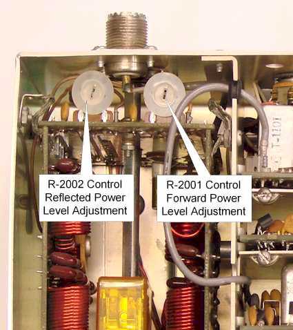
Power Meter Calibration
To calibrate the internal Watt Meter you
will need an external Watt Meter with know accuracy like a
Bird Model 43 Watt Meter with a 100 watt or higher element
for the 3-30Mhz range. Connect your
known accurate watt meter to the antenna connector and a 50
ohm dummy load to the other side of the watt meter.
Set the transceiver to the 14Mhz band and select the CW
mode. Next key the transmitter and using the
front panel Carrier Level control adjust the power output to
exactly 100 watts as indicated on the external watt meter.
While the transmitter is still keyed adjust R2001 on the
Low-Pass Filter Board until the internal transceiver watt
meter indicates 100 watts. Make sure
the front panel watt meter switch is set to the "Forward"
position before making the adjustment. Do not
keep the transmitter keyed for more that a few seconds at a
time to prevent over heating the power amplifier. Next
remove the antenna connection to the external watt meter.
Quickly key the transmitter and turn down the power level
using the Carrier Level control until the green ALC lamp
goes out. At that point take note where the
internal watt meter in indicating with the "Forward"
position. Next select the "Reflected"
position and set R-2002 on the Low-Pass Filter Board to the
same internal watt meter indication as noted in the
"Forward" position.
|
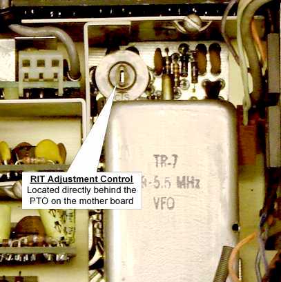
RIT Centering Adjustment
To calibrate the front panel RIT
control, first turn "ON" the RIT function and set the RIT
knob pointer to the center, or straight-up position.
Then zero-beat the receiver to the internal calibrator
signal and the nearest 25khz increments. Once you set
the zero-beat, then turn "OFF" the RIT function and adjust
control R-24 on the Parent Board to zero-beat with the
internal calibrator signal. R-24 is located on
the Parent Board just behind the PTO as shown in the picture
with the Display Board removed. There is
also an access hole on the Parent Board from the bottom side
to access R-24 with the Display Board mounted in position. |
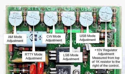
Mode Frequency Adjustments
Each of the mode adjustments is a voltage
adjustment which is sent to the Pass-Band Tuning Board to fine
tune the radio to the exact offset. Since all these
voltages are derived from the +10 volt regulator, before making
these mode adjustments, first make sure the +10 volt regulator is
set to exactly 10 volts. To set the +10 volt
regulator use a digital volt meter attached to the 1K resistor
lead at the top right corner of the board adjacent to the
regulator circuit adjustment. Next adjust the mode controls, first
select the desired mode with the front panel switch, and make
sure the PBT button is released. Next tune the receiver
to the exact frequency which corresponds with the selected mode as
shown below. As the receiver approaches
the desired frequency a beat note will be heard.
The beat note should be set to zero when the receiver is on the
right frequency. It may be necessary to turn
up the audio to hear the beat note when it approaches
"zero-beat" because the tuning will be on the edge of the
filters bandwidth. Selecting a wide bandwidth filter
like the AM mode filter will increase your ability to hear the
beat note.
AM = 13,695.0Mhz RTTY=13,697.5Mhz CW=13,694.2Mhz LSB=13,696.4Mhz
USB=13,693.6Mhz
|
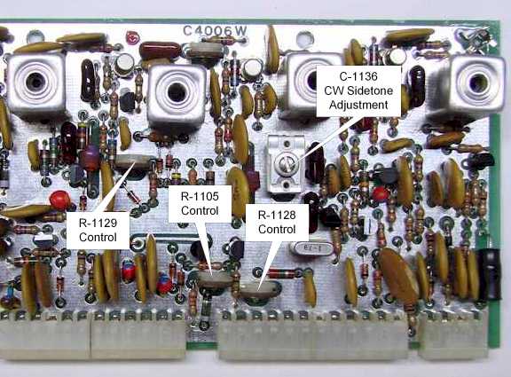
S-Meter, IF gain, and CW Mode
Off-Set Adjustments
| To make the S-Meter adjustments first
remove the rear cage area top cover. Next select the AM
mode and remove the antenna connection. The AM mode
is used to prevent the BFO signal leakage from interfering with
the adjustment. Next turn R-1128 (Meter Zero) fully
clockwise. Next turn R-1129 (AGC Pedestal) fully
clockwise. Next turn R-1129 counter-clockwise until the
S-Meter level increase by two S-Units. Next
adjust R-1128 for an S-Meter reading between 0 and 1 S-Unit,
make sure its at least slightly above the zero. Next
turn the front panel RF gain control fully counter-clockwise.
Then adjust R-1105 (Meter Sensitivity) for a full scale S-Meter
reading of 80dB. Now turn the RF Gain control
fully clockwise and make sure the S-Meter reading is still
between 0 and 1 S-Unit. If it is not, repeat
the alignment procedure again. Because of the interaction
between the controls it may be necessary to go through the
alignment procedure a couple of times.
To adjust the CW side-tone offset select the
CW mode and key the transmitter, make sure the power level is
turned to a low level setting so not to damage the Power
Amplifier. While the transmitter is keyed adjust
C-1136 for an 800Hz side-tone. The C-1136 is
accessible through the CW jack on the rear panel. Using a
small metal screwdriver you can key the transmitter and make
this adjustment through the CW key jack. |
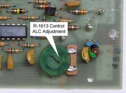
ALC Adjustment
To adjust the transmitter ALC, select the
14Mhz band, and select the CW mode. Connect a 50 ohm
dummy load to the antenna connector. Next key the
transmitter and turn the Carrier Level control to maximum
output. Next adjust R-1613 on the ALC Board, which
is mounted to the Low-Pass Filter Board, to between 140 and 150
watts output. Un-key the transmitter and set
the Band Switch to the 28.5Mhz band. With the
Carrier Level control still at maximum, adjust the
R-2227 control on the power amplifier Predriver Board to a point where
the front panel green ALC light just goes out. Do not
adjust R-2227 beyond this point or transmitter instability will
result. The picture shows the R-1613 on the ALC Board. Refer to the
Power Amplifier section on page 7 of this article for the
location of the R-2227 control on the Predriver Board of the
Power Amplifier. |
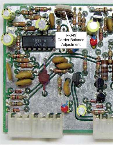
Transmit Carrier
Balance Adjustment
This adjustment minimizes
the transmitter carrier level signal in the LSB and USB modes.
The best way to make this adjustment is by using an external
receiver tuned to the transceiver's transmit frequency.
To make the adjustment first select the USB mode and turn the
Microphone Gain control to minimum or counter-clockwise.
Next key the transmitter and listen to the signal with the other
receiver. If the Carrier Balance needs adjustment you
will hear a low level signal. Adjust R-349,
located on the Transmit Exciter Board, for minimum signal level.
Even after this adjustment has been set to minimum in some cases
a small amount of signal still may be detectable.
This adjustment can also be
made by sampling the transmit signal at the antenna connection
with a RF Voltmeter or oscilloscope. If you use this
method make sure the transmitter is properly terminated into a
50 ohm load. |
Next Page
Previous Page
|