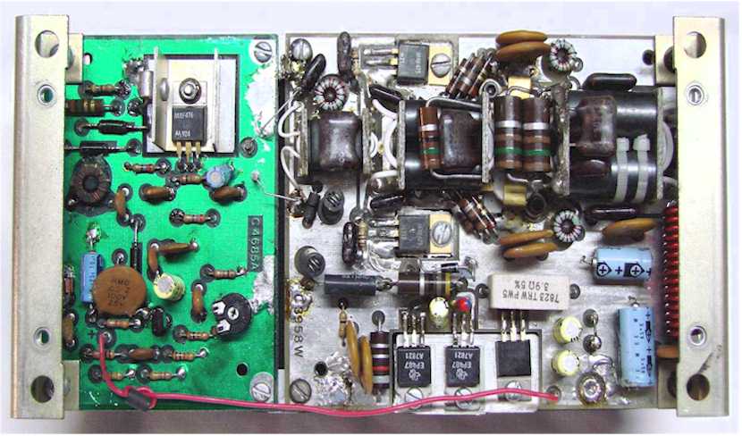
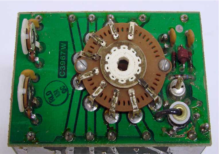
| The Power Amplifier Board consists
of two separate circuit boards mounted to a large heat sink.
The Pre-driver Board on the left side of the picture
amplifies the transmit signal to a sufficient level to drive
the power amplifier board. The output drive level is
controlled from the on-board drive level control.
This board operated at 13.8VDC and is switched on during the
transmit mode through the relay mounted on the Low-Pass
Filter Board. The power
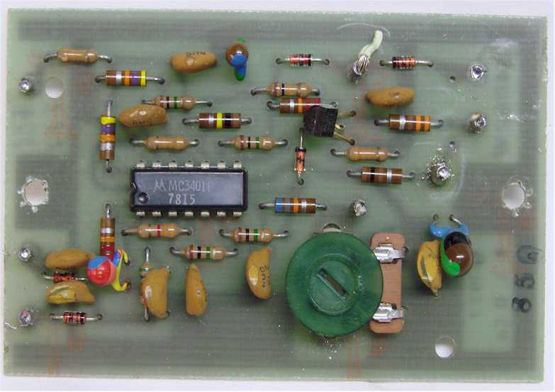
amplifier board, right side in picture, has a pair of driver
and final amplifier transistors. Each transistor pair
operates in push-pull to provide a good balance for proper
circuit gain and flatness across all frequencies from 1.8 to
30Mhz. The 13.8VDC supply voltage for the
amplifier is
connected directly to primary power and is not switched.
The bias circuit, transistors across the bottom of the board
in the picture, provide sufficient bias to to hold the
amplifier transistors in cut-off during receive mode.
The Power Amplifier Board takes a very low level signal,
typically between 100 and 200 millivolts, from the
radio and amplifies that to well over 100 watts of output
power.
The ALC circuit, located on the High-Pass Filter Board controls the
overall gain of the Pre-driver Board to limit the output
power to around 100-120 watts output.
Even though this amplifier is capable of producing power
levels greatly exceeding 100 watts, its not recommended.
Running higher power levels over time will significantly
shorten the life of the transistors. Typical
output power levels of the transceiver are 110-125 watts on
all bands below 15 meters, and 80 to 100 watts on all bands
15 meters and above. |