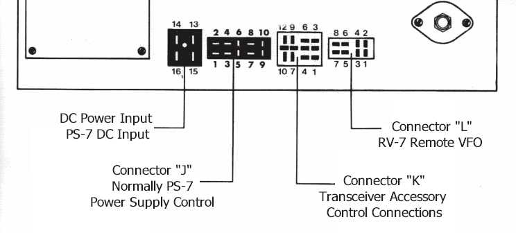
| The four large Cinch Jones plugs
across the back of the transceiver accommodate various
accessories for the radio. The pin-out
connections of each plug is listed in the manual, but here I
will discuss a few other options to consider beyond the
standard accessories.
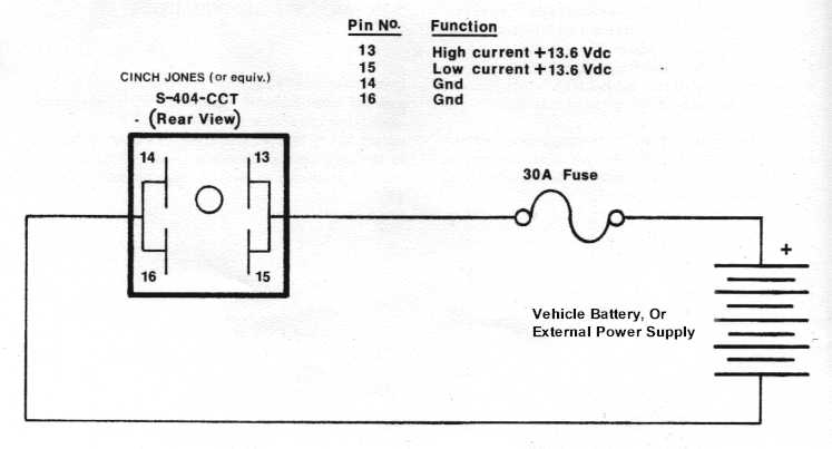
Starting with connector "J" this
connector is the AC switch and control functions for the
PS-7 matching Power Supply. For those not
using the PS-7, pin #8 is used to key an external amplifier,
this pin goes to ground, Pin 10, when the transmitter is
keyed. On this connector, pin #9 is the
ALC input for the external amplifier, ground is pin #10.
The internal power switch comes out to pins #1 and #2, this
can be used to switch any external power supply for the
radio.
Connector "K" supports the use for
several station accessories. Some of the
more useful functions include, switched +10VDC on transmit is
found at pin #1, continuous +13.8VDC is found on pin
#9, transmitter key is pin #10, (transmitter keyed when
grounded), and pin #3 is chassis ground.
On this connector pin #7 is the antenna input for the VLF
bands, ground is pin #3. This is the antenna input for
receiving frequencies below 1.5Mhz. As noted in
the manual the SO-239 antenna connector does not support the
VLF input to the receiver.
Connector "L" is specific to the RV-7
remote VFO and only provides signal and switching functions
for that accessory. Not much useful
functions outside its intended use with the RV-7. |
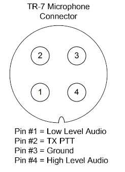
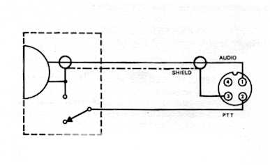
 chassis
either through the microphone or as a separate lead
connected to Pin #3. The TR7 microphone
connector has an internal 1000 ohm resistor between pins #1
and #4. Pin #4 is used for high
level audio inputs and should be used with amplified
microphones over using pin #1. Pin #4 would also
be used as the audio input from other devices such as the
output from a tape recorder having high audio output.
chassis
either through the microphone or as a separate lead
connected to Pin #3. The TR7 microphone
connector has an internal 1000 ohm resistor between pins #1
and #4. Pin #4 is used for high
level audio inputs and should be used with amplified
microphones over using pin #1. Pin #4 would also
be used as the audio input from other devices such as the
output from a tape recorder having high audio output.