WB4HFN Home Page Drake Technical Tips Menu Drake Home Page Collins Home Page Heathkit Home page
![]()
|
Inside The Drake TR-7 Transceiver by: Ronald Baker / WB4HFN Contents Page 1 Page 2 Page 3 Page 4 Page 5 Page 6 Page 7 Page 8 Page 9 >Page 10< Page 11 Page 12 Page 13 Page 14 Page 15 Page 16
Poor Man's AM Filter Modification
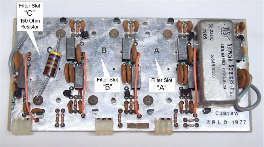
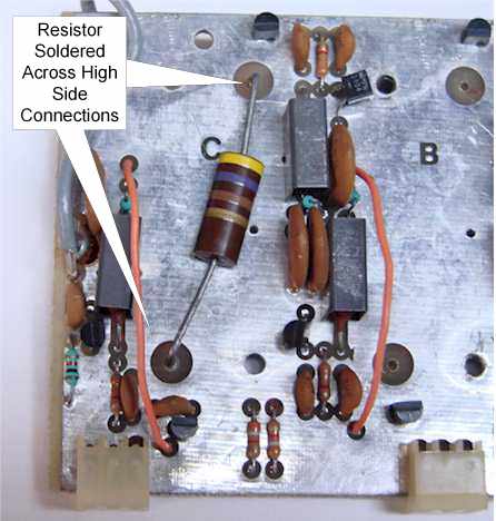
The picture on the left is a close-up of the wide band AM mode modification. Shown here is a 450 ohm resistor, but a lower value such as a 150 ohm resistor will also work fine. In some cases the lower value will allow a little more signal to pass but may be more prone to overloading the receiver with a strong signal. The larger value will pass less signal and is less susceptible to receiver overloading. The higher value would be better choice for radios which exhibits high signal gain or considered a 'Hot" receiver. In this picture a 2 watt, 450 ohm resistor installed in slot "C". Any wattage resistor will work since the power rating is not a factor, and can be installed in any open slot. The 2 watt resistor is typically used because the lead size is approximately the same size as the filter pins which makes a nice fit.
All Band Transmit Modification
TR-7 Quiet Fan Modification The original Drake FA-7 Fan option was intended to be used for the extended transmit mode like RTTY and AM. Under normal SSB and CW operations the fan option wasn't required, though possibly needed for heavy "contesting" type of use. When the Drake FA-7 fan accessory was installed it did a good job keeping the radio cool, however it was a noisy fan. The constant roaring noise level was objectionable in an otherwise quiet ham shack. Several modification surfaced which seemed to help but required modifying the radio, adding parts and in some cases an entire circuit board to control the fan. Though effective in reducing the noise most were not simple installation. The basic problem was the fan ran from 110VAC which being an AC motor made it harder to electronically control or switch. Also, the FA-7 fan ran the entire time the transceiver was powered on whether cooling was needed or not.
Now there at two different thoughts on two different subjects around the installation and operation of the fan. Should the fan blow inward or outward, and should it run all the time or just during transmit. Blowing in or out is more a personal choice and everyone has an opinion on that subject. Since the fan mounts either way, that choice is your decision. Powering the fan you will need to decide whether you want it on all the time or on only during transmit, the wiring difference is where you place the red positive power lead. I choose to have the fan blow inward and to run all the time because the fan noise is just a whisper, and virtually undetectable. The constant air flow keeps the radio at a more even temperature for better operating stability.
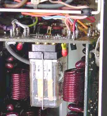
This picture shows the back side of the fan connector This show the tight area behind the antenna relay Before starting make sure the radio is completely disconnected from all power. In this modification I used the "FAN" receptacle next to the fan. First I cut back and tape both of the existing wires connected to the two terminals. Tape well because there is 110VAC across those wires when using the PS-7 Power Supply. Next route the red & black fan power leads through the fan blade opening and over the divider as shown in the picture. Next cut the leads to length leaving some slack and solder the black wire to the lower terminal and the red wire to the upper terminal. Next take a small length of wire and solder one end to the lower terminal where the black wire is attached. Solder the other end to the chassis ground terminal just to the left of the fan connector. Next take a long length of red wire and solder that to the upper connection where the red fan lead wire is soldered. Route the length of wire across the back of the panel to the other side bringing the end in front of the low pass filter, input board, where the antenna relay is mounted.
After this connection is made, recheck the installation and reassemble the radio. The fan connector now also serves as a +12DVC low current power source with continuous or switched +12VDC depending on how the fan was wired.
|
 The
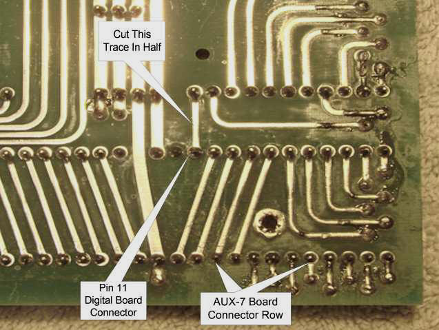
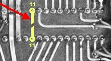
modification is as simple as cutting one circuit trace on
the Parent Board. The trace you cut runs between pin
11 of the Digital Board connector and pin 11 of the Transmit
Exciter Board. From the bottom of the
transceiver locate the copper trace as shown in the picture.
The location is along the the front edge, right corner,
looking at the radio bottom side up. Using a
razor blade cut the trace halfway between the board
connectors as shown in the picture. Once this
trace is cut the TR-7 transceiver is capable of transmitting
on any frequency tuned on the display or VFO setting.
This modification will now allow you to operate on all the
new WARC bands. Just remember, "KEEP IT LEGAL",
operate only in the approved Amateur Radio bands.
The TR-7 in not FCC type-accepted to operate outside the
Amateur Radio bands.
The
modification is as simple as cutting one circuit trace on
the Parent Board. The trace you cut runs between pin
11 of the Digital Board connector and pin 11 of the Transmit
Exciter Board. From the bottom of the
transceiver locate the copper trace as shown in the picture.
The location is along the the front edge, right corner,
looking at the radio bottom side up. Using a
razor blade cut the trace halfway between the board
connectors as shown in the picture. Once this
trace is cut the TR-7 transceiver is capable of transmitting
on any frequency tuned on the display or VFO setting.
This modification will now allow you to operate on all the
new WARC bands. Just remember, "KEEP IT LEGAL",
operate only in the approved Amateur Radio bands.
The TR-7 in not FCC type-accepted to operate outside the
Amateur Radio bands.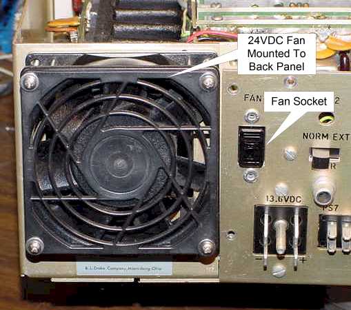 I wanted to come up with a fan modification that cooled,
was quiet and easy to install without modifying the transceiver.
This way the modification could be quickly removed putting the radio
back into its original condition. First I decided to
use a DC powered fan and it had to be the same size as the FA-7 for
mounting purposes. The fan itself is a standard 5" box
fan available in a wide variety of operating voltages. I
first tried using a 12VDC fan but found the noise level to be about the same as the original FA-7 fan. For 90% of all
transmitting conditions the high velocity fan was an over-kill,
so I went with a 24VDC fan operating at 12VDC to lower the RPM's. The 24VDC fan starts up
and runs fine on 12VDC. It also runs slower and much quieter and
still provided sufficient air flow to keep the radio cool under extended
transmitting modes.
I wanted to come up with a fan modification that cooled,
was quiet and easy to install without modifying the transceiver.
This way the modification could be quickly removed putting the radio
back into its original condition. First I decided to
use a DC powered fan and it had to be the same size as the FA-7 for
mounting purposes. The fan itself is a standard 5" box
fan available in a wide variety of operating voltages. I
first tried using a 12VDC fan but found the noise level to be about the same as the original FA-7 fan. For 90% of all
transmitting conditions the high velocity fan was an over-kill,
so I went with a 24VDC fan operating at 12VDC to lower the RPM's. The 24VDC fan starts up
and runs fine on 12VDC. It also runs slower and much quieter and
still provided sufficient air flow to keep the radio cool under extended
transmitting modes. 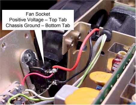
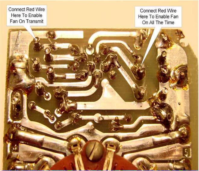 On the back side of the antenna relay board you have two
terminals providing switched and unswitched +12VDC. Solder
the red wire to the unswitched voltage terminal for continuous fan
operation and to the switched voltage terminal to operate the fan during
transmit only. See close-up picture of this area for
the exact terminal. Working in this area is very tight
and can be difficult to access.
On the back side of the antenna relay board you have two
terminals providing switched and unswitched +12VDC. Solder
the red wire to the unswitched voltage terminal for continuous fan
operation and to the switched voltage terminal to operate the fan during
transmit only. See close-up picture of this area for
the exact terminal. Working in this area is very tight
and can be difficult to access.