|
Inside The Drake TR-7
Transceiver
by: Ronald Baker / WB4HFN
Contents
Page 1 Page 2
Page 3 >Page 4<
Page 5 Page 6
Page 7
Page 8
Page
9
Page 10
Page 11
Page 12
Page 13
Page 14
Page 15
Page 16

The Up-Converter Board
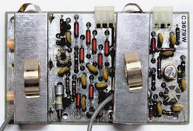
| The Up-Converter Board serves a dual
function. In the receive mode the incoming
signal from the antenna passes through High Pass Filter
Board to the input of the Up-Converter board.
The Up-Converter board samples the locked frequency from the
Translator Board, mixes that with the incoming signal to
produce the 1st IF frequency with an output at 48.05Mhz.
In the transmit mode the input to this board is the 48.05Mhz
transmit IF frequency. This IF signal is mixed
with the same locked frequency from the Translator Board, to
produce an output signal on the operating transmit
frequency. The transmit output of
this board travels back through the High-pass Filter Board
and the pin-diode switch to the transmit pre-driver stage. |
The VCO Board
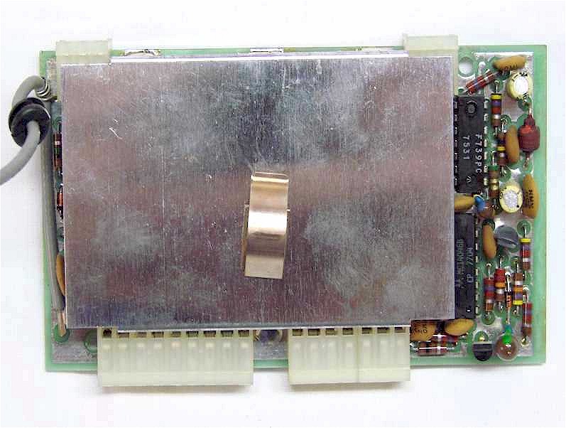
| The VCO Board (Voltage Controlled
Oscillator) function is to generate the final mixing
frequency, (Injection Frequency), which is sent to the
Up-Converter Board to produce the actual receive and
transmit operating frequencies. This board
has two voltage controlled oscillators, one for the lower
band range of 0 to 15Mhz, and a 2nd for the higher band
range of 15 to 30Mhz. Other than the actual
operating frequency range both oscillators operate in the
same manner and are selected according to the operating band
selected. This board also contains
the phase detector and loop filter portion of the
synthesizer used to produce a "locked" frequency condition
when the VCO is tuned to the correct injection frequency.
|
The Translator Board
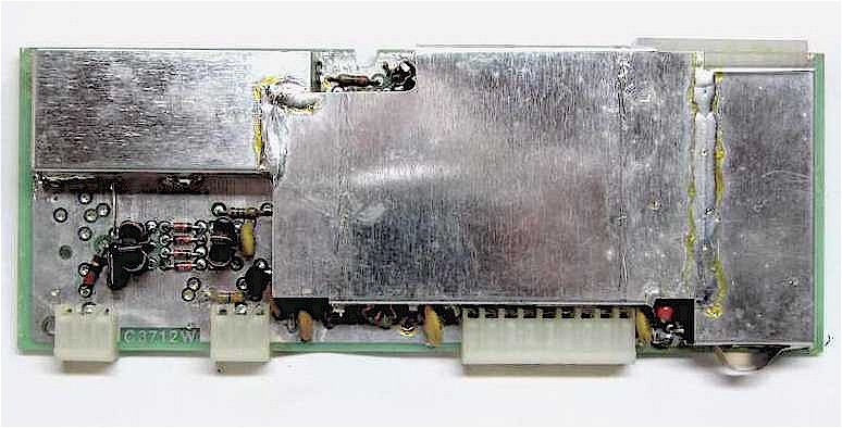
| The Translator Board combines signal
inputs from three sources which produces a output signal
between 3 and 32.5Mhz, exact frequency depending on the set
tuning range of the transceiver. This output
signal is then sent to a programmable divider network which
produces a 500Khz signal used to phase lock the VCO master
oscillator.
The first two signal inputs, the PTO
signal, 5.05 to 5.55Mhz, and the 40Mhz reference from the
Pass-Band Tuning Board, are mixed together to produce a
signal between 45.05 to 45.55Mhz. This signal is
filtered and applied to a 2nd mixer stage where its mixed
with the master VCO signal between 48.05 to 78.05Mhz.
The output of the 2nd mixing stage, a signal between 3 to
32.5Mhz, is applied to a programmable divider network.
The programmable divider is programmed by the Digital Board
to divide the input frequency between 6 to 65, depending on
the 500Khz selected tuning range of the transceiver.
The output of the programmable divider is a constant 500Khz
signal when the synthesizer is phased locked to the VCO
tuning frequency. |
The PTO Assembly
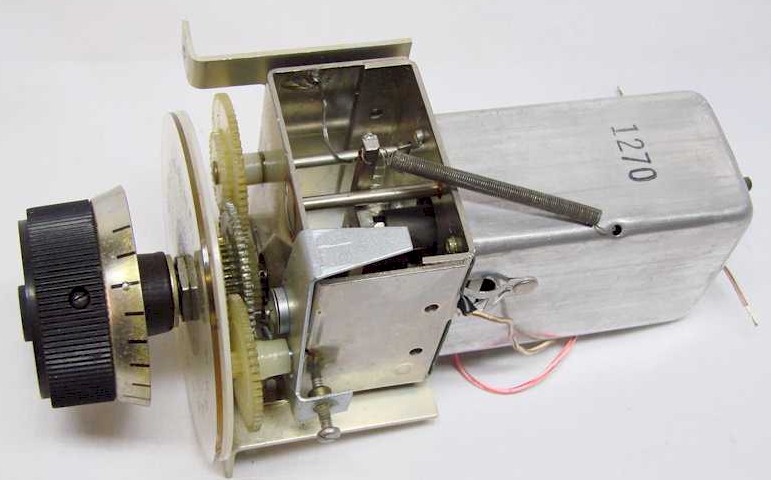
| The PTO ( Permeability-Tuned
Oscillator) provides a 5.05Mhz to 5.55Mhz injection signal
to the frequency synthesizer circuit. The
VCO Board tracks the frequency of the PTO to provide an
overall 500Khz tuning range for the radio. The PTO is
calibrated and temperature compensating to provide a highly
stable signal with a minimal drift. The
PTO includes a set of tuning dials calibrated to the PTO to
provide a very accurate frequency display at the front
panel. |
Next Page
Previous Page
|