|
Inside The Drake TR-7
Transceiver
by: Ronald Baker / WB4HFN
Contents
Page 1 Page 2
Page 3 Page 4
Page 5 >Page 6<
Page 7
Page 8
Page
9
Page 10
Page 11
Page 12
Page 13
Page 14
Page 15
Page 16

The Pass-Band Tuning Board
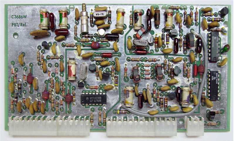
| The Pass-Band Tuning Board is a
multi-function board which generates the master oscillator
frequency, mixer injection signals and secondary signals
through a frequency divider network. In addition
the board does the "Mode" function switching and controls
the manual pass-band tuning adjustment. Of the many
functions, this board generates the 40Mhz master oscillator
signal of which most every part and function of the radio is
connected to. This 40Mhz high stability crystal
oscillator signal source is considered the heart beat of the
radio, problems here affects all other parts and functions
of the radio in some way. One output of this
signal is sent to the frequency divider network which
outputs the 500Khz signal for the synthesizer lock reference
and a 25Khz signal used for the receiver "25Khz Calibrator"
function. This boards also feeds
the mixer circuits to produce the 53.696Mhz injection signal
to the 2nd Mixer Board and the 5.645Mhz BFO signal to the
Transmit Exciter Board. For the
Pass-band Tuning function this board contains a 13.696Mhz
VCXO, or Voltage Controlled Crystal Oscillator, which is
capable of pulling the crystal oscillator frequency +/- 3Khz
depending in the bias voltage applied.
Preset bias voltages for each Mode of Operation of the radio
is switched through a quad IC switch which is controlled by
the front panel "Mode" switch. These
voltages are preset with individual "Mode" adjustment
controls located on the Power Supply Board.
These preset voltages set the VCXO to the exact offset
frequency for the "Mode" selected from the front panel.
When the Pass-Band Tuning is set to the manual tuning mode,
the front panel "Pass-Band" control varies this bias voltage
controlling the VCXO frequency. This allows the
receiver to be manually adjusted from the low side of the
crystal filter (LSB) through the high side (USB) of the
crystal filter pass-band range. |
The IF/Audio Board
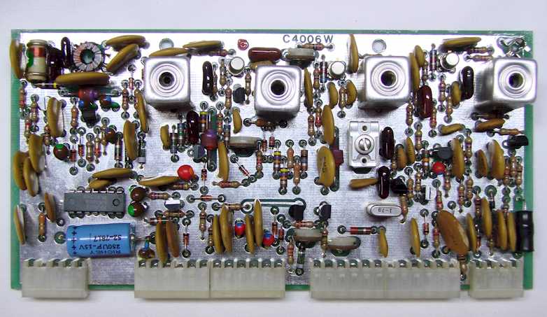
| The IF/Audio Board supports multiple
functions in receive and transmit modes.
In the receive mode the board takes the 5.645Mhz IF signal
from the Filter Board, provides additional gain and AGC
control and produces a signal level voltage for the S-Meter
functions. The function of the AGC
(Automatic Gain Control) is to provide a constant level
signal to the detector stage with varying input
signal level to the receiver. The resulting output of the detector stage is demodulated receiver audio
which is then sent to the audio amplifier and speaker.
In the transmit mode the board uses a crystal oscillator to
generated the 5.645Mhz transmit IF carrier signal.
In the AM and CW modes this signal is sent directly to the
Filter Board, and in the SSB and RTTY modes the signal also
includes the mode frequency off-set before going to the
Filter Board. |
Transmit Exciter Board
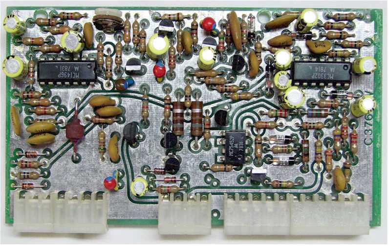
| The Transmit Exciter Board provides
microphone audio amplification, controls the transmitter VOX
functions, produces the modulated transmit IF frequency, and
provides the +10 volt transmit/receive switching.
Microphone audio from the front panel connector is sent to
this board where the audio is amplified and sent to the
balanced modulator input and the VOX circuits.
The VOX circuit is controlled through the setting of three
front panel controls, VOX Gain, VOX Delay and Anti-VOX.
With these adjustment the VOX circuit is adjusted to key the
transmitter with signal input from the microphone, controls
the transmit delay, and prevents the receiver audio from
keying the transmitter. The amplifier microphone
audio feeds the balance modulator and mixed with the
5.645Mhz transmit IF carrier signal from the IF/Audio board
to produce a modulated transmit IF signal.
The output of the balanced modulator is then sent back to
the Filter Board and through the 2.3Khz SSB filter to limit
the signal bandwidth of the transmit signal. |
Next Page
Previous Page
|