|
Inside The Drake TR-7
Transceiver
by: Ronald Baker / WB4HFN
Contents
Page 1 Page 2
Page 3 Page 4
Page 5 Page 6
Page 7
Page 8
Page
9
Page 10
>Page 11<
Page 12
Page 13
Page 14
Page 15
Page 16

The TR-7 "Pin Diode" Dilemma
| The infamous and ever eluding TR-7 "pin diode" problem is
probably the single most difficult repair to make in the radio.
Troubleshooting and finding the pin diodes is the easy part,
getting at then to replace is a definite challenge.
The pin diodes are found on the High-Pass Filter assembly, just
behind the S-meter and in the same compartment with the internal
speaker. The pin diodes are used for low level signal switching
for the 25Khz Calibrator on the front board of the filter
assembly, and on the rear board, low level signal switching to
and from the Up-Converter. The front board is
the board closest to the front of the radio directly behind the
S-Meter. The rear board is located on the other end of the
filter assembly. |
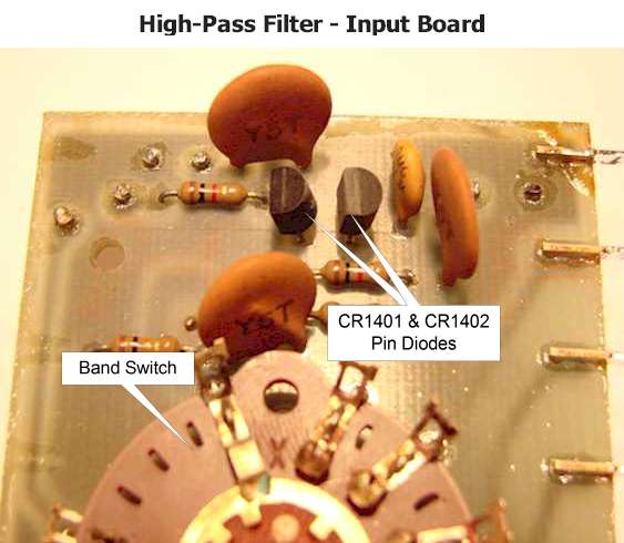
High-Pass Filter - Front Board
The High-Pass Filter, front board, switches the Calibrator
signal to the Up-Converter through CR1401 and CR1402, (MPN3404 Diodes).
Referring to the front board diagram to the right, you see there are three input
signals going to the input switch side of the filter. The VLF Antenna
input, (Red Arrow Line), transmit & receive signals to the Up-Converter
(Green Arrow Line), and the Calibrator signal, (Blue Solid Arrow Line).
When the front panel Calibrator switch is selected, that sends +10VDC through
resistor R1401, (Blue Dash Arrow Line), which forward biases the two pin diodes
creating a low resistive signal path for the calibrator signal to flow to the
Up-Converter input. When the Calibrator switch is de-selected this
removes the voltage, reverse biasing the pin diodes, which stops the Calibrator
signal from going through the pin diodes.
Accessing these pin diodes and soldering is very difficult
and requires a certain amount of skill and patience getting them replaced.
The best method I can recommend is to follow the disassembly procedure detailed in
the TR-7 Service manual.
|
The picture below shows the location of the
two pin diodes on the High Pass Filter - Front Board. |
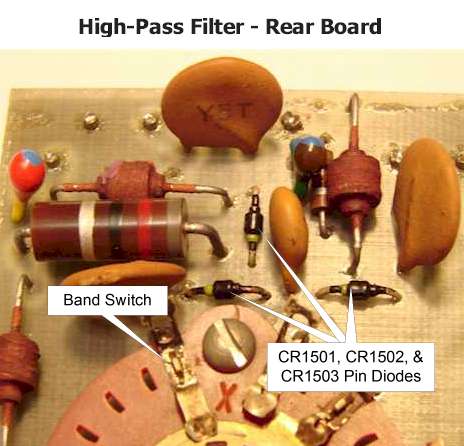
High-Pass Filter - Rear Board
The High-Pass Filter - Rear Board switches the low level
signal to the Up-Converter from the antenna connector in the receive mode and
the signal from the Up-Converter to the Power Amplifier module in the transmit
mode. On this board the pin diodes are a high frequency switching
diode, number UM9401. The 13.6VDC switch control voltage to turn on and off the
pin diodes comes from the a set of relay contacts in the antenna relay.
In receive mode a 13.6VDC control voltage is applied through
RFC1504, (Green Dash Arrow Line) which forward biases pin diodes CR1502 and
CR1503, allowing the input signal from the antenna connector to pass though to
the input selector switch, (Green Solid Arrow Line), and the filter assembly.
In the transmit mode a +13.6VDC control voltage is applied
to RFC1501, (Red Dash Arrow Line), forward biasing pin diode CR1501, allowing
the low level transmit signal to flow to the Power Amplifier, (Red Solid Arrow
Line).
Some of the more common problems with the pin diodes on this
board is when they short or start leaking. When this occurs
low power output and low receiver sensitivity will both be noticeable and having
a greater affect as you go higher in frequency.
|
Pictured below is the High Pass Filter -
Rear Board showing the physical location of the three pin diodes, CR1501,
CR1502, and CR 1503 |
Troubleshooting Pin Diode Problems
|
Troubleshooting a pin diode problem will be a bit tricky
from the standpoint of getting to them to take measurements.
On the Front Board, when the Calibrator switch is selected
that puts a positive voltage on the anodes of both CR1401 and
CR1402. As you go from the anode to the
cathode you will see a small reduction in voltage,
typically a .6 to 1 volt drop across each diode. If
a total loss of voltage is found across one or both pin diodes,
that diode is probably open, and with measurable voltage but no voltage difference
across them, the
pin diode is shorted. In either case the defective diode
is preventing the signal from reaching in band switch
input. When the Calibrator switch is deselected all
voltage should be removed. One common problem caused by one or both of these diodes
going bad or leaking is poor receiver sensitivity and low power output on 10
meters. Typically CR1402 shorts and causes the input signal to
be grounded through capacitor C1404. This effect is most noticeable
on 10 meters. Troubleshooting the Rear Board will
be more difficult since there is a switched voltage to deal with
on transmit and receive. In either mode there will be a
measurable voltage at the input of the band switch, but with the
voltage source coming in from two different directions.
The best way to check these pin diodes is to lift the cathode of
the pin diode opposite to the mode being tested at the input to
the band switch. This way the receiver pin diodes
will not induce any effect on the transmitter side being tested,
and vise-versa. In either the transmit or
receive mode you should be able to follow the voltage from anode
to cathode to the band switch. If the positive
voltage is not measurable at the cathode, the diode is
defective. Before replacing the pin diode
cathode you previously lifted from the board, measure the
receiver sensitivity or power output. After replacing the
the pin diode cathode you should still see approximately the
same results. If the result is noticeably
different one of the pin diodes on the opposite side is probably
leaking pulling down the input signal.
Following this procedure on both the receive and transmit modes
will detect open and leaking pin diodes. |
Next Page
Previous Page
|