|
Inside The Drake TR-7
Transceiver
by: Ronald Baker / WB4HFN
Contents
Page 1 Page 2
Page 3 Page 4
Page 5 Page 6
>Page 7<
Page 8
Page
9
Page 10
Page 11
Page 12
Page 13
Page 14
Page 15
Page 16

The Digital Board
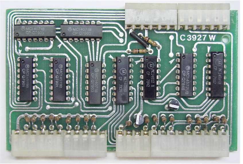
| The function of the Digital Board is
to decode the data from the band switch and produce the
frequency range data which is then sent to the frequency
synthesizer. The frequency synthesizer
takes this data and produces the corresponding tuning range
of the transceiver as determined from the band switch
setting. This board also controls the switching
between the "Normal" tuning ranges and the tuning range
input from the AUX Program Board. |
The AUX-7 Board
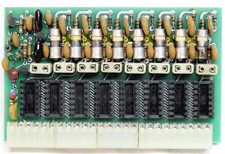
| The AUX-7 Board is an accessory
board that accommodates the programming for up to eight
additional 500Khz tuning ranges for transmit and receive
functions. The board also supports up to eight
channels for fixed frequency operation.
All tuning ranges and fixed channels are selectable from the
front panel "AUX Programming" switch. The
eight 500Khz tuning ranges are programmable using the
plug-in diode array modules. Each of the eight
fixed frequencies are crystal controlled by installing the
appropriate crystal on the board. Each crystal
position has an individual trim capacitor to zero in the
correct frequency. |
The Digital Display Board
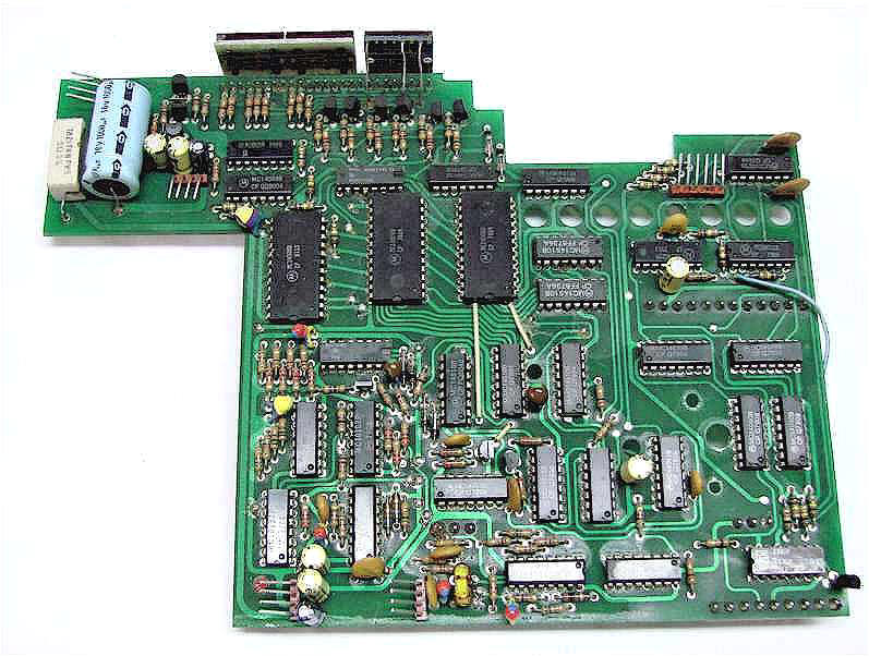
|
The Digital Display
Board provides two major functions for the transceiver.
First it provides full frequency coverage for all
frequencies from 500Khz to 30Mhz and generates the frequency
range data beyond the Amateur Radio bands.
Second, the board displays the operating frequency in a
digital format. Both functions work
independently of each other, a failure in one section does
not affect the other. This board mounts over
the top of other circuit boards plugged into the Parent
Board. Because of the board size and
mounting makes this board very
difficult to remove and replace. The board must
be precisely placed to fit the front panel display and align
the pins on the bottom side. Take care when
removing or installing this board, its very easy to misalign
the bottom side pins. Applying power with this board
not properly installed could cause significant damage to the
board and the transceiver. |
The Power Supply Board
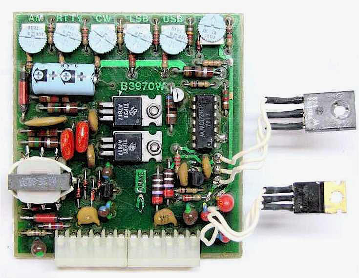
| The Power Supply Board takes the
primary input power, typically 13.8VDC, and outputs four
different voltage levels. The +10VDC and
+5VDC outputs are internally regulated on the board.
The +24VDC and the -5VDC are unregulated and are produced
from a DC to DC inverter circuit running at 23Khz.
This DC inverter circuit included the two board mounted
transistors in the center of the board and the small
transformer on the right side near the bottom.
The Power Supply Board also contains the
voltage divider adjustments for the fixed pass-band tuning
control lines. These adjustments are the
transceiver mode fixed frequency off-set adjustments that
fine-tune the offset to the exact frequency. There
are separate frequency adjustments for the AM, RTTY, CW, LSB,
and USB modes. |
Next Page
Previous Page
|