|
Inside The Drake TR-7
Transceiver
by: Ronald Baker / WB4HFN
Contents
Page 1 Page 2
Page 3 Page 4
>Page 5< Page 6
Page 7
Page 8
Page
9
Page 10
Page 11
Page 12
Page 13
Page 14
Page 15
Page 16

The Second Mixer Board
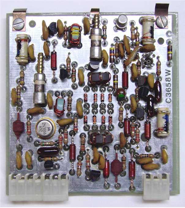
| The 2nd Mixer Board serves a dual
function depending on transmit or receive.
In the receive mode the 48.05Mhz IF signal from the
Up-Converter Board is applied to the input of the 2nd Mixer
Board. The injection signal for the mixer
is the 53.696Mhz signal developed on the Pass-Band Tuning
Board. The output of the mixer takes the
difference of the two signals, the 5.645Mhz IF signal,
filters and amplifies that signal and sends it to the Filter
Board. In the transmit mode the
process is reversed. The Mixer Board takes the
5.645Mhz transmit IF signal and mixes that with the
53.696Mhz injection signal from the Pass-Band Tuning Board.
The board filters the difference of those two frequencies,
and outputs the 48.05Mhz IF signal to the Up-Converter
Board. |
The IF Switching Board
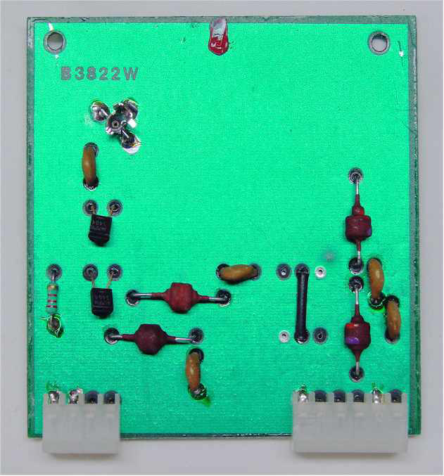
| This slot on the transceiver Parent
Board accommodates two boards. If the
accessory Noise Blanker Board is installed it provided both
the IF switching function described here and performs the
noise blanking function, described below.
Pictured here is the IF Switching
Board which is used if the Noise Blanker accessory in not
installed in the radio. This board provides the
transmit/receive switching for the 5.645Mhz IF signal.
In the receive mode the 5.645Mhz from the 2ND Mixer Board is
switched through this board to the IF Selectable Filter
Board. In the transmit mode it takes the
5.645Mhz transmit IF signal from the Transmit Exciter Board
and switches that to the 2nd Mixer Board. |
Noise Blanker Board
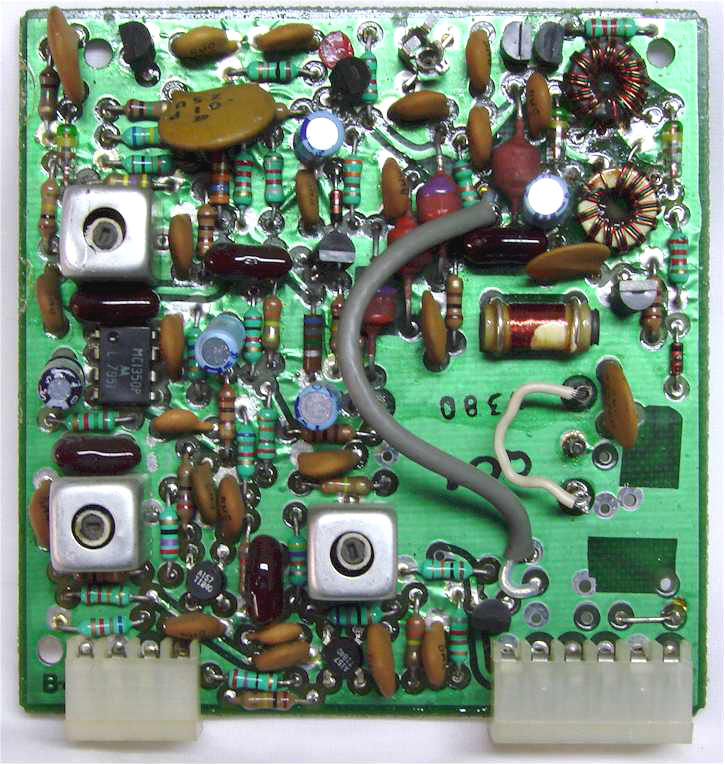
| The Noise Blanker Board is an accessory
which is a plug-in replacement for the IF Switch Board and also
provides signal noise processing during receive mode.
This board provides the same signal switching functions as
detailed in the IF Switch Board description.
In addition, in the receive mode this board samples the 5.645Mhz
IF signal to detect pulsing type noise spikes such as ignition
noise generated from a automobile engine. When the
noise processor detects noise peaks it turns off the IF
amplifier during the spike to eliminate the pulse noise.
The noise processor is very effective for short duration noise
spikes in the range of 50 milliseconds or less in duration. |
The Filter Board
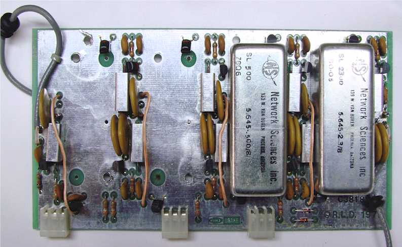
| The IF Selectivity Board servers a
dual function depending on transmit or receive.
The board is designed to accommodate up to four different
crystal filter bandwidths. The board comes
standard with the 2.3Khz SSB filter mounted in the first
position. The other three positions are for
accessory filters which were purchased separately and
installed by the end-user. The other
filters available include a 6Khz or 4Khz AM filter,
1.8Khz RTTY filter (also used for a narrow SSB filter),
1000Hz RTTY filter, 500Hz CW filter and a 250Hz CW filter. Each of the
accessory filters were mounted to the board and soldered in
place. In the receive mode each of the filters
is independently selectable from the front panel push
button switches. Pictured above this
board has mounted to it the SSB filter, far left, and the
500Hz CW Filter in the second position.
In the receive mode the board routes the 5.645Mhz IF signal through the selected
filter to limit the bandwidth of the received signal
according to the mode of operation. In the
transmit mode the board was hard wired to only select the SSB
filter for all transmitting modes of operation.
Note, that went removing the top cover
shield, ultimate selectivity of the crystal filter is
somewhat compromised due to outside signals leaking around
the filter. Make sure the top shield
cover is in place for normal operations. |
Next Page
Previous Page
|